

Introduction: Bluetooth Zoom/OBS Controller


Not long into the pandemic we were heavily into Zoom for church services, and so to facilitate the management of online sessions I built a Zoom control box. Views and likes took off quite spectacularly, and at the time of writing it has clocked up over 43,000 views and 20 people have said they made it. (No doubt a good few others did too.)
Ever since, I've wanted to build a Bluetooth version so as to avoid the dangling cable. This would need a Bluetooth-capable controller instead of a cheap Arduino Pro Micro, rechargeable battery and charging circuit. So if the cable doesn't bother you, you might as well stick to my original design, but wire-free is always nice.
In researching how to make a Bluetooth version it transpired that people have made very similar controllers for OBS (Open Broadcast Studio), which is used for managing multiple video feeds. This can be controlled, like Zoom, with special hot-key combinations, in fact professional controllers can be had for a tidy sum. But all you have to do is redefine the key combinations generated by the different buttons for my controller to operate with OBS - or for that matter, with any other program which accepts hot keys, including Teams, Google Classroom and other teleconferencing solutions.
Supplies
You may want to vary the design, but here are the supplies I used:
- ESP-WROOM-32 development board.This comes is several configuratioons, but the 30 pin breadboard-friendly version is the easiest to work with.
- 6 or 7 push buttons. Search for "12mm round push button switch" or "PBS-33b" for the ones I used. Various sellers offer a set of 6 different colours but you can also get an orange one from some sources.
- 5-pin rotary encoder.
- 2 3mm LEDs - green and blue (or your preference).
- Resistors:
- 1k 2-off
- 4.7k 4-off
- 27k 1-off
- 100k 1-off
- 503035 LiPo battery with 2-pin JST connector.
- Matching JST socket.
- TP4056 charger module.
- 3.3k 0603 or 0805 surface mount resistor.
- 3mm Red/Green LED, common anode.
- MicroUSB breakout board.
- DPDT miniature slide switch.
- MicroUSB lead.
- 20 way (or more) rainbow ribbon cable.
- Project box. The one I used was 125x80x32mm from AliExpress but you can use any, or make your own. Mine came without screws. If yours is the same you'll need 4 M3.5x20mm.
- Self-adhesive rubber feet.
As for tools and supplies, I used:
- Soldering iron, solder, wire cutters and strippers, screwdrivers, adjustable spanner etc.
- Drill. A step cone drill bit is very good for enlarging a pilot hole to the size needed for the push buttons.
- Needle file, for shaping the appertures needed for the slide switch and microUSB connector.
- Hot melt glue gun, superglue and 2-part epoxy glue.
- Label printer.
The ESP-WROOM-32 supports capacitive touch inputs, and if you prefer, you can make touch pads out of self-adhesive copper foil instead of push buttons. In fact I used this method for initial development before the box and buttons arrived, with everything simply mounted on a piece of cardboard. It worked well, but I preferred the positive feel of push buttons - while managing a complicated Zoom session you don't want any accidents due to accidentally brushing a touch pad.
Step 1: The Design

After a little research it seemed that the readily available and fairly cheap ESP-WROOM-32 microcontroller was best suited to my needs. It has Bluetooth built-in and can run directly from a single Lithium polymer cell.
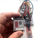
Initially, I mounted the ESP-WROOM-32 on a piece of card, with 6 touch pads and a rotary controller as proof of concept and for software development before I found a suitable box. Unfortunately I didn't think to take a photo of it (above) until I'd removed the microcontroller and installed it in the final build.
I also needed to incorporate a charging circuit. On a previous project I used one of the very cheap TP4056 charger modules but I'd since read that it's not a good idea to charge a lithium battery while it's powering a load. We all do that all the time with our laptops, tablets and phones, but they have a more sophisticated charge controller. The TP4056 terminates the charge when the current drawn by the battery drops to 10% of the mAHr capacity, but if the load is also drawing current this may never happen, leading to overcharging. If you left it in this state for an extended period the battery may be damaged, and in the worst case, catch fire.
The solution is to only charge it when the switch is off. In this state, the battery is only connected to the charging module, and in fact the microUSB port will be powering the ESP-WROOM-32 as well as the charger, so you can continue with your Zoom session if you want to.
Step 2: Construction


Unless you use the bare module, the ESP-WROOM-32 from most vendors comes with pin headers already soldered on for use on a breadboard. This would require a significantly deeper box, so I removed the pin headers. It's not possible to heat all the pins at once to unsolder them, so the easiest way is to ease the black plastic of the pin headers away from the board along its length, using a sharp blade. Continue until it cames right off the pins. You can then easily unsolder the pins one by one.
To make the holes in the box for the buttons and the rotary encoder, much the easiest way that I've found is to use a step cone drill. (Search on eBay if you've not come across these.) This allows you to enlarge a small pilot hole very cleanly by a millimetre or two at a time. It has a standard hex shaft so you can use it in a pillar drill, or by hand with a universal screwdriver handle.
Hopefully, if you drill 3mm holes for the LEDs, they will be a snug fit and can be secured with a drop of superglue. If they're a bit loose you will have to carefully position them while the glue sets.
For the holes for the switch and the MicroUSB breakout board I drilled a pilot hole then enlarged and shaped it with a needle file.
The MicroUSB breakout board has mounting holes but it's probably easier to glue it in place. But don't do this until you've wired it up and tested it. (I'll tell you why later.) To withstand the force of plugging in a MicroUSB lead you need to use 2-part epoxy glue, and you need to have a lead plugged into it while the glue sets to make sure it's properly positioned. I don't recommend superglue as the breakout board may not sit sufficiently flush with the base of the box for it to grip, and it can easily run into the socket, ruining both the socket and the lead plugged into it. (I speak from bitter experience!)
The charging module is most easily held in place with hot melt glue. I could have done the same with the ESP-WROOM-32, but chose to screw it to one of the mounting bushes in the base of the box. But don't make my mistake - the head of the screw was a little too big and damaged the adjacent Boot button. Fortunately this is not normally needed.
The battery is held in place with double-sided tape. I soldered a JST socket to a scrap of stripboard to make the connection. Soldering in the battery connection didn't seem a good idea, given that I might have made a mistake in the wiring.
Apart from the buttons and the rotary encoder, it's probably easiest to wire them up and test before fixing them in place.
Step 3: Wiring Up


A length of rainbow ribbon cable is much the easiest and neatest way of wiring up the buttons and the rotary encoder. A spare strand can be used for all the other connections.
If you're using the PBS-33b push buttons, you may find the plastic softens rather easily. Be sure to tin the wires before soldering, and apply heat and solder to the push button pins for as short a time as possible. I don't remember having this problem on my original Zoom Control Box so I suspect there are multiple manufacturers who use different plastics.
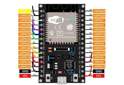
The ribbon cable makes it easy to colour code all the other push button and rotary controller connections and the connections to the LEDs. The colour scheme I used (as shown in the photo) wasn't quite the best, so I suggest you use a scheme summarised below:
| Colour | Connection | ESP-WROOM-32 Pin | Notes |
| Black | Ground | GND | |
| Brown | Button 1 | 13 | |
| Red | Button 2 | 12 | |
| Orange | Button 3 | 14 | |
| Yellow | Button 4 | 27 | |
| Green | Button 5 | 33 | |
| Blue | Button 6 | 32 | |
| Violet | Button 7 | 35 | 4k7 pullup to 3.3V |
| Grey | Rotary Encoder C | 34 | 4k7 pullup to 3.3V |
| White | Rotary Encoder B | 39 | 4k7 pullup to 3.3V |
| Black | Rotary Encoder A | 36 | 4k7 pullup to 3.3V |
| Brown | Blue LED | 2 | Via 1k to blue LED anode, LED cathode to Gnd |
| Red | 3.3V | 3.3V | 1k to green LED anode, cathode to Gnd |
From a length of around 20cm of ribbon cable, remove all but 13 strands, with black on one side and red on the other. I found it helpful to tack it to the inside of the box lid between the pushbuttons, using hot melt glue. You can then pull back and trim the strands to length as required.
Ground connections
Start by connecting all of the following together:
- one pin on each of the push buttons
- on the rotary encoder, the middle pin of the 3 on one side, and
- one of the 2 pins on the other side.
You can use a spare strand of the ribbon cable, or solid core hook-up wire. Connect the black strand on one side of the ribbon cable to one of these connections.
Buttons and rotary encoder
The next 7 strands will be brown through to violet. Connect these in turn to the other pins on the 7 push buttons. (From the front of the box, I numbered the top row of buttons 1, 3 and 5 (left to right) and the bottom row 2, 4, 6 and 7.)
Connect the grey wire to the unconnected pin of the two on one one side of the rotary controller.
With the orientation of the rotary encoder such that the three pins are on the left, connect the white wire to the top pin of the three and the next black wire to the bottom.
The rotary encoder has two mounting tags on the other two sides. These are not used.
LEDs
Trim the shorter leads of the two LEDs and solder them together.
Trim and solder a 1K resistor to each of the longer leads of the LEDs.
Connect the next brown wire to the other end of the resistor on the blue LED.
Connect the next red wire to the other end of the resistor on the green LED.
Pull-up resistors
Most of the pins on the ESP-WROOM-32 have internal pull-up resistors which can be configured when they are used as inputs. These are required to ensure that the pins see a login "1" when the button is not pressed. However, the input we are using for button 7 and the three inputs for the rotary encoder don't have pull-ups and we must supply our own.
Take four 4k7 resistors. Solder one to button 7 (already having a violet wire connect to it), and the other three, one each to the three non-ground pins on the rotary encoder (to which you have already soldered the grey, white and black wires). Solder together the free ends of all four resistors and connect them to the red wire already connected to the resistor on the green LED.
ESP-WROOM-32
Finally, solder the other ends of all 13 strands to the ESP-WROOM-32 as in the table above.
And now...!
There's still the LiPo battery and charger to wire up, but you already have enough to test. And I know how much you love to see something working as soon as possible!
Step 4: Programming and Test
To program the ESP-WROOM-32 you need to download and install the Arduino IDE (Integrated Development Environment). It's a free download from https://www.arduino.cc/en/software
Also, download the file BTZoomButtons.ino, which is attached to this step. If you double-click this file (wherever you downloaded it) it should launch the Arduino IDE and create a sketch with the same name (less the .ino suffix).
Should that not work, launch the Arduino IDE. It will create a skeleton sketch with today's date in the name. Save it as BTZoomButtons. Close the Arduino IDE, then copy BTZoomButtons.ino into the sketch folder, overwriting the existing file. It should be My Documents\Arduino\BTZoomButtons if you installed the IDE with default file paths.
Relaunch the IDE. If it doesn't launch with the BTZoomButtons sketch, click the File drop-doen menu and select Sketchbook, where you should find it. You now have to install the libraries it needs.
To install the libraries for the ESP-WROOM-32, click on the Tools dop-down menu and select Board, and then Boards Manager. Scroll through the board libraries offered until you come to esp32 by Espressif Systems. Hover the mouse over it and click Install.
If you don't find esp32, in the Arduino IDE, select File - Preferences, and to the Additional Board Manager URLs, append:
,https://dl.espressif.com/dl/package_esp32_index.json
You also need a software library. Again, click on Tools, then Manage Libraries. This is similar to the boards library except that there are many more to choose from. In the search box, type esp32, then scroll through the list until you come to ESP32 BLE Arduino by Neil Kolban. Install it in the same way.
You now need to select the right board. Under Tools - Board, select ESP32 Arduino, then ESP32 Dev Module.
You also need to select the right com port. Before connecting the ESP-WROOM-32 to your computer, in the Arduino IDE, select Tools - Port and note which COM ports are shown. Dismiss this menu by clicking anywhere else, then take a microUSB lead and connect the ESP-WROOM-32 to a USB port on your computer. Once again, select Tools - Port, and one more COM port should show up. Select this. (If the red power LED on your ESP-WROOM-32 came on but no more COM ports appeared, your microUSB lead is probably a charging lead, not a data/sync lead.)
You can now upload the code. Under Sketch, click Compile. This will take a minute or two, at the end of which it should upload the sketch, showing progress as a percentage as it does so. The blue LED should then flash twice to show the sketch is running.
Attachments

Step 5: Testing With Zoom

Your Zoom control box is perfectly usable as it is if you were to power the ESP-WROOM-32 with a power bank and MicroUSB cable or from your computer, but that would somewhat defeat the object of making it wireless.
On your computer, under Settings, Devices, make sure Bluetooth is on, and click Add Bluetooth or Other Device. Choose Bluetooth as the type of device to add. You should see ZoomBox. Click on it to connect. The blue LED on your Zoom box should light after a short pause, showing that it's connected.
First, check that the volume control works. Press the knob to mute or unmute sound. Now you can check that the buttons work.
Launch Zoom, and click on the Settings cog wheel icon in the top right and select Keyboard Shortcuts. Against each of the shortcuts that you want to use, select the Enable Global Shortcut check box. This means that the keyboard shortcut will be recognised and actioned by Zoom even if you're currently interacting with another program. Should a shorcut key combination clash with one you use with another program you might be using at the same time, you can select the key combination and change it. You will then have to change the Arduino sketch to match.
You can now start a Zoom meeting and check out all the buttons.
Step 6: Battery and Charger


Setting the charge current
The charger modules as commonly sold are generally programmed for a charging current of 1A, which is too much for a 500mAHr LiPo battery. A little bit of fine soldering is required to change this. With care, it isn't that hard, but as an alternative, you can either use a 3.7V LiPo battery intended for a small remote control quadcopter or similar, or one of greater capacity (1000mAHr). Either should be able to stand the faster charging rate.
To reduce the charging rate, locate R3 on the TP4056 module, marked in green in the photo. It will probably be marked 122 (1.2k), which is the value for a 1A charge rate. If in doubt, you can check its value with a multimeter and corfirm that it's the right one by checking that the two ends are connected respectively to the two middle pins of the chip marked 4056. I suggest a 3.3k resistor to give a charge current of 360mA or you could use a 2.7k resistor for a slightly faster charge at 440mA.
Remove R3 by applying a hot soldering iron with a relatively large bit to the whole resistor, or both ends alternately until it comes away. Or lay a piece of solder wick over it to spread the heat of the iron to both ends. Don't force it or you may lift the copper circuit track, making it much more difficult to install the replacement.
Wipe away excess solder from the solder pads, leaving just a little, then add flux with a flux pen (essential for surface mount soldering). Place the replacement surface mount resistor in position, spanning the two solder pads. Whilst keeping it in position with a small screwdriver blade gently pressed onto it, melt the solder on one pad with a fine tip on your soldering iron. Add just a little more solder if necessary. (People with 3 of 4 hands generally find this quite easy, but regular human beings can still do it with a little patience.) Repeat at the other end of the resistor - but you shouldn't need the screwdriver if you successfully soldered the first end. Examine both ends with a magnifying glass, and check that the solder has run up each end of the resistor.
Charge status LEDs
The TP4056 module has 2 LEDs (ringed in their respective colors in the photo) to indicate charging or charge complete. You could mount the module with the LEDs behind a hole in the box to make them visible, or maybe even use a lightpipe. I chose to remove them and replace them with a 3mm red/green common anode LED.
To do this, remove the LEDs in the same was as you removed the resistor above. Using fine enamelled copper wire, connect either of the two adjacent exposed pads to the LED common anode (the middle, longest lead), the other pad of the original blue LED to the shortest of the LED's 3 wires and the the other pad of the original red LED to the remaining lead.
Step 7: Power Wiring

The remaining parts are most easily wired up against the schematic above.
To connect to the microUSB socket on the ESP-WROOM-32 you will need a microUSB lead. Cut it a few inces from the plug, then remove the outer insulation, revealing the 4 colour coded wires. Take great care not to cut any of the wires in removing the outer insulation. You can discard the screen, wrapped around all the wires.
The switch has 2 rows of 3 pins. The two middle ones are the ones going to the ESP-WROOM-32. An outer pin at one end of one row and the other end of the other row go to the charger module.
For a rough and ready indication of the battery charge level, on the ESP-WROOM-32, connect a 27K resistor from D15 to VIN and 100K from D15 to GND.
With a digital multimeter, measure the voltage between OUT - and OUT + on the charger. Divide this by the voltage between OUT - and D15 (the junction of the 2 resistors). You should get a value in the region of 0.79.
In the Arduino sketch, near the top, you will find a line
#define BATTDIVIDER 0.775
Change the number (which is what I got) to the value you got, then recompile and re-upload the sketch.
The blue LED will flash once a second when the battery gets down to 10%, and if it flashes twice a second, you urgently need to put it on charge.
Step 8: Fault-finding
If it doesn't immediately work, the first thing to do is to double-check your wiring. Are there any slivers of solder or strands of stranded wire shorting anything out? Are all the solder joints good?
If the blue LED is flashing continuously this probably means that one (or more) of the pull-up resistors is missing or not properly connected. If you chose to use different pins on the ESP-WROOM-32 or added any buttons, maybe you used yet another pin not having an internal pull-up.
As an initial test or if you're not sure all the buttons are working, in the Arduino sketch at around line 44, find a line
//#define TEST
Delete the double slash, recompile and re-upload. Launch Notepad or a word processor before it makes the Bluetooth connection.
Each of the 7 buttons should now generate a single letter, a - g.
Step 9: Modifications
Changing the codes
If you want to use it with OBS or another program instead of Zoom, towards the end of the sketch you will find a series of case statements. These define the keys to press and release for each hotkey function for each of the 7 buttons. Change them as required.
If you wanted to it'd be quite easy to add a switch to switch between Zoom and Teams or Google Classroom. I'll leave that as an exercise for the reader.
More or fewer buttons
If you want fewer buttons you can just leave the relevant pins on the ESP-WROOM-32 disconnected - but you will still need the pull-up on button 7 unless you consistently delete the button 7 definitions in the sketch, and change the definition of NUMBUTTONS.
If you want more buttons, choose as many inputs as you need on the ESP-WROOM-32. This pinout reference will help you choose. Increase the definition of NUMBUTTONS, and wherever you see BTN7, add more as required. Also, add the hotkey definitions to the case statement. If you want lots more buttons, there's a version of the ESP-WROOM-32 development board with 36 pins instead of 30.
No volume control
If you don't want to include the volume control, all you need to do is find
#define VOLUME
and prefix it with a double slash.
Touch control
If you want to use touch control instead of push buttons, find the line
//define TOUCH
and delete the double slash. The same pins will then be configured for touch input, except for 35 (button 7), which doesn't support touch. If you want 7 touch pads, the 7th needs to be connected to pin 20.
Enhanced battery control
I said it's a bad idea to charge the battery while it's powering the ESP-WROOM-32. If you're afraid you won't always remember this and might leave it on and charging for a week, this article describes what you should do.
The battery gauge is very rough and ready. If you want something more accurate, you could try including a SparkFun MAX17043 module or DFRobot DFR0563 (which uses the same chip). There are cheap SparkFun (and possibly DFRobot) clones available from eBay or AliExpress, but these mainly seem to be fake and don't work with the available Arduino libraries. My experience in this is corroborated by various posts in Arduino forums, none of which seem to provide a work-around for the clones.


