

Introduction: Bluetooth and Magnetic Bell


You will find in this Instructable everything needed to reproduce this fun little magnetic bell controlled through Bluetooth.
But before starting, I would like to tell you more about the origin of this project.
The origin
I live in the center of a big city, and I am very sensitive to noise pollution. Most of this noise pollution comes from cars (engines running or horns honking). And as a pedestrian and cyclist, I am very exposed.
While observing vehicles in the streets, I noticed that buses and trams (at least in France, but probably also elsewhere) have 2 types of horns: a loud horn to warn other vehicles, and a bell to warn pedestrians. But why don't cars have this warning bell? It's definitely a mission for me, I had to do one. My first idea was to create a device integrated into my car, but it was too much work and not very reproducible. So I came up with the idea of a Bluetooth doorbell (activated from a button inside the car), with magnets to place it anywhere on my car.
This is the list of the goals I had when starting this project:
- Raising public awareness of noise pollution in cities;
- Reducing noise pollution, by using this Bluetooth bell on my car;
- Avoiding to scare pedestrians and cyclists in the streets;
- Create a better atmosphere in the streets. This is a device that makes people smile, and this is important :)
Features
As you can see, there are two boxes that I call "Bluetooth button box" and "Bluetooth bell box" all along this Instructable. You probably already guessed most of the features, but here they are once again:
- Bluetooth activated bell;
- Magnetic boxes, to fix on any ferromagnetic surface;
- Powered with 9V batteries.
Supplies
For 3D printing:
- A 3D printer (or any service to print the pieces for you);
- PLA.
For electronic circuits:
- Perfboards;
- 2x Arduino Nano boards;
- 1x push button;
- 2x HC-05 Bluetooth modules;
- 1x SG90 servo motor;
- 1x switch button;
- 1x 10kOhm resistor;
- 1x voltage regulator (L7805CV);
- 1x 100nF capacitor;
- 1x 300nF capacitor
- Wires.
Other:
- 1x bike bell;
- 8x neodymium magnets (8 mm in diameter, 3 mm thick);
- 14x M3 screws (10 mm long);
- 8x M3 nuts.
- 4x M2 screws (10 mm long);
- 4x M2 nuts;
- 2x 9V batteries (I use rechargeable batteries).
Step 1: Pairing HC-05 Modules


The first step in this project is to make sure both HC-05 modules pair correctly. There are a lot of datasheets and tutorials on the internet, and this one was particularly useful to me.
Here is a summary:
- Upload a blank sketch on the Arduino board;
- Unplug the Arduino board;
- Connect the HC-05 module as shown on the picture;
- Press the reset button on the HC-05 module and plug the Arduino board while holding the reset button (long slow blink indicate AT command mode);
- Open Arduino IDE and monitor, make sure its BAUD rate is 38400, and select "Both NL and CR";
- Now you need to configure a module as a slave, and the other one as a master:
- For the slave:
- Type "AT+ROLE=0" in the monitor to set the module as a slave. The monitor should return "OK".
- Type "AT+ADDR?", and write the address to use it later with the master module. Change ":" with ",";
- For the master:
- Type "AT+ROLE=1" in the monitor to set the module as a master. The monitor should return "OK".
- Type "AT+CMODE=0", to connect to only one device;
- Type "AT+BIND=address". With address the address you obtained from the slave module previously.
- For the slave:
Now, to make sure both modules pair correctly, plug both boards with their modules. Make sure to switch the wires connecting RX and TX:
- Arduino RX is now connected to HC-05 TX;
- Arduino TX is now connected to HC-05 RX.
If everything goes fine, you should observe that the modules enter in paired mode.
Pairing mode (short rapid blink):

AT command mode (long slow blink):

Paired mode (two short blink, synchronyzed between both modules):

Now I recommend to make the full circuits (shown in steps 2 and 4) on a breadboard to make sure everything work fine.
Step 2: The Bluetooth Button (electronics)
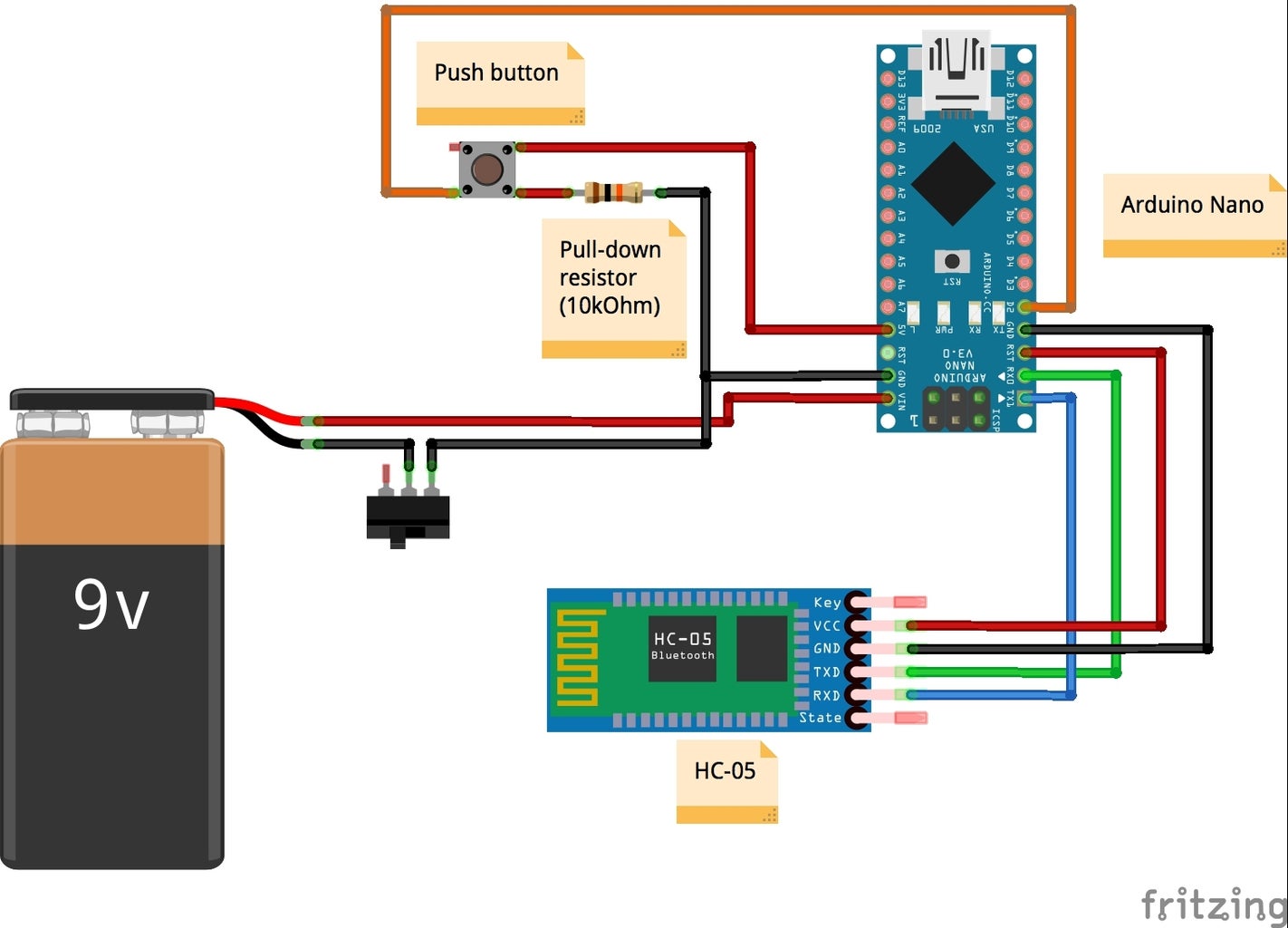


The circuit is quite simple: the Arduino Nano board is powered with a 9V battery, with a switch in between. Then there is a simple push-button with a pull-down resistor. Finally, there is the HC-05 Bluetooth module (in master mode) to communicate.
I soldered the circuit on a perfboard. If you want to use the same boxes I designed and 3D printed (see next steps), then you will have to stick to the dimensions I used:
- The perfboard should be contained inside a disk with a diameter of 78 mm (black grid below). For example, a perfboard with a size of 55x50 mm is perfect;
- The perfboard is attached to the box with two M3 screws that are located at 30 mm from each other, centered on the perfboard. The holes are 3.3 mm in diameter.
- Finally, the push button should be placed inside a circular area of 20 mm in diameter, centered on the perfboard (see the green grid below).
For a better understanding, see the drawing below:

Finally comes the Arduino code. It is a modified version of the "Button" Arduino sketch. You can download it below.
/*
  Bluetooth and magnetic bell: https://www.instructables.com/member/Matlek/
  Bluetooth button sketch
  The following code is a modified version of the "Button" example (http://www.arduino.cc/en/Tutorial/Button)
*/

const int buttonPin = 2;     // the number of the pushbutton pin
const int ledPin =  13;      // the number of the LED pin
int buttonState = 0;         // variable for reading the pushbutton status
String state;

void setup() {
  Serial.begin(38400);
  pinMode(ledPin, OUTPUT);
  pinMode(buttonPin, INPUT);
}

void loop() {
  if (Serial.available() > 0) { // Checks whether data is comming from the serial port
    state = Serial.read(); // Reads the data from the serial port
  }
  // read the state of the pushbutton value:
  buttonState = digitalRead(buttonPin);

  // check if the pushbutton is pressed. If it is, the buttonState is HIGH:
  if (buttonState == HIGH) {
    digitalWrite(ledPin, HIGH);
    Serial.write(1);
    delay(1000);
  } else {
    digitalWrite(ledPin, LOW);
    Serial.write(0);
    delay(1000);
  }
}
Attachments

Step 3: The Bluetooth Button (box)


The "Bluetooth button box" is composed of five 3D printed parts, which I am going to describe in details:
- The main box;
- The lid (to close the box);
- The battery cover;
- The button base (which is the first part of the button);
- The button top (the second part of the button);
I think it is much more relevant to describe the features I imagined and added, rather than showing you how to design the pieces. This way you can have a better idea of how I design my projects.
There are plenty of softwares and tutorials available online. If you are a beginner, try Tinkercad. To go even further, you can try Fusion 360 or FreeCAD.
1 - The main box
The box is the main part of the project, and I designed it so that both the "Bluetooth button box" and the "Bluetooth bell box" have the same size, but with slight differences. Besides the aesthetic aspect, its main goal is to maintain and protect the electronic circuit.
I would like to draw your attention to the following details:
- The box has a hole on its top, through which the button base passes. I made sure it is slightly bigger than the base of the button, but not too tight so that the button can be pushed and released without getting stuck;
- There are 2 holes to attach the perfboard, with a diameter of 3.1 mm. This is small enough so that M3 screws can be directly screwed into the plastic. Of course, the holes will be damaged after many times, but it does the job if you screw/unscrew the perfboard only a few times.
- There are 4 holes to attach the lid of the box, with a diameter of 3.3 mm. This is enough to let the M3 screws enter easily. You can also notice a pocket below, to place nuts. I designed these pockets so that the nuts tightly fit, and stay in place. Also, the triangular shape you can see was designed on purpose so that no supports are added during slicing (and before 3D printing), thanks to the angle. This is a quite useful feature since the pockets containing the nuts have to be with exact dimensions, and supports can modify this dimensions if not removed properly.

2 - The lid
Then comes the lid. This part is the same on both the Bluetooth button and Bluetooth bell boxes, so I am just going to describe it here. The main goal of the lid is to close the box, it contains the switch to turn ON/OFF the device, and a pocket to place the 9V battery.
The main characteristics of the lid are the following:
- I designed a pocket so that the battery cover can be removed more easily;
- There is also another pocket to place the switch. It is deep enough so the switch does not stick out, and large enough to access the switch;
- On the other side of the switch pocket, I made two other pockets to place M2 nuts, and holes adapted for M2 screws. This is to attach the switch to the lid;
- You can also see that there is a border all around the battery pocket, in order to maintain the battery cover;
- Magnets are placed in holes specially designed so they stay in place;
- Finally, all around the lid there is a small border to help to place the lid correctly and aligned with the boxes (with holes for the M3 screws perfectly aligned).

3 - Battery cover
The battery cover helps to protect the battery, and make sure the battery stays in place. This is inspired from common battery covers used on remote controls (such as TV remote control for example). On one edge, it has 2 protruding pads so it is maintained on the lid. On the opposite edge, I designed a flexible pad to clip it on the lid.

4 - Button base
The button base is just an assembling of 2 cylinder. The thinner cylinder passes through the hole of the box. The larger cylinder helps to maintain the base inside the box (since it is larger). This larger cylinder is used to press directly on the push-button used on the circuit described previously. And there is also a hole through this base with a diameter of 3.1 mm, to place an M3 screw. I originally made this hole in order to adjust the Z position of the button inside the box, but I finally found out it was not needed.
5 - Button top
And finally there is the button top. It is just a disk, with a hole on its lower face (to attach the button base). On its upper face, I made 2 different designs (on 2 different versions of the button). To print these shapes in another color (as you can see the bell and the border of the button are white, while the button itself is black), I have added the M600 command inside my GCODE before printing. This M600 command is used to change the filament during a print. I usually place the STL file in my slicer, check at which layer the bell is being printed, export my GCODE, and open it in a text editor. I search for the layer identified previously and add "M600" in the GCODE.


Step 4: The Bluetooth Bell (electronics)


The second circuit is composed of another Arduino Nano, powered with a 9V battery, with a switch. Again, there is an HC-05 module (in slave mode) to communicate. There is also a servomotor that is used to ring the bell. Since the servomotor might require more current than the Arduino can provide, I have used a voltage regulator to provide 5V to the servomotor from the 9V battery.
I made the circuit on a perfboard. Once again, if you decide to use the box I designed, you have to use the same dimensions:
- The perfboard has to fit inside a disk of 79 mm in diameter. A perfboard with a size of 55x50 mm is perfect;
- Drill 4 holes with a diameter of 3.3 mm (to attach the perfboard to the box with M3 screws), and use the same dimensions as shown below.

The code is quite simple: if the Arduino receives a "1" through Bluetooth with the HC-05 module, it means the button was pushed. The servomotor then moves from the rest position to another position to ring the bell. Then it goes back to the rest position. You might change these positions according to the bell and the servomotor you use.
The code can be downloaded below.
/*
  Bluetooth and magnetic bell: https://www.instructables.com/member/Matlek/
  Bluetooth bell sketch
*/

int state = 0;
#include <Servo.h>
Servo myservo;

void setup() {
  myservo.attach(5);
  pinMode(LED_BUILTIN, OUTPUT);
  Serial.begin(38400); // Default communication rate of the Bluetooth module

}

void loop() {
  if (Serial.available() > 0) { // Checks whether data is comming from the serial port
    state = Serial.read(); // Reads the data from the serial port
  }
  Serial.println(state, DEC);
  if (state == 1) {
    myservo.write(70);
    delay(500);
    myservo.write(140);
    delay(1000);// wait for a second
  }
}
Attachments
Step 5: The Bluetooth Bell (box)


The Bluetooth bell box is very similar to the Bluetooth button box. It is composed of 4 parts:
- The main box;
- The bell attachment;
- The lid (see step 3);
- The battery cover (see step 3).
1 - The main box
It has the exact same shape as the Bluetooth button box (a cylinder with the same diameter and same height). Here are a few important details to notice:
- Instead of the hole for the button base, the top of this box has a T-shape hole. This hole is designed so the servomotor cable can get inside the box;
- In this box, there are 4 holes to attach the perfboard, with 3.3 mm in diameter;
- Finally, once again there are the same pockets to place the M3 nuts described previously.

2 - Bell attachment
The box was initially designed in one piece, combining the box and the bell attachment. But during the slicing (for 3D printing), the initial piece required too much supports. Therefore I decided to split the box into 2 individual parts and glue them together with cyanoacrylate glue. I have uploaded both versions so you can choose the one you prefer.
This bell attachment contains a pocket in which the SG90 servomotor can be placed. There is also a hole to let its cable passes through.
And there is a cylinder to attach the bell on it.


Step 6: Assembly of the Parts


Once you have all the pieces, all you have to do is put them together. You can refer to the video in step 1.
You will need the M3 screws and nuts, and a screw driver.
Step 7: Supports


To finish, I also made supports to place the boxes when they are not used. They are very simple, and tight enough so the boxes remain fixed. I initially wanted to put them on the dashboard of my car, but finally changed my mind because it can get really hot in summer, and plastic will probably melt.
Attachments

Step 8: Conclusion and Comments


To conclude, I really enjoyed doing this project, and I am very happy with the result. I have used it a few times already, and it will definitely stay in my car.
There are a few details I would like to change on future versions:
- Better indicators to make sure the Arduino boards are ON, and the HC-05 modules are synchronized. When making the project I originally though the light indicators on the devices would be visible through the thin yellow plastic I used for 3D printing. This is the case in my dark workshop, however, they are impossible to see under sunlight because the ambient light is too bright. So it might be a good idea to add holes to the boxes or additional LEDs as better indicators.
- Better grip with the magnets. The current version works well, but adding additional magnets, or even thinner layer below the magnets would definitely improve the grip of the boxes on ferromagnetic surfaces.
Finally, I would like to end this instructable with an image of the different failures I faced during this project. Every project is the result of a learning process that sometimes requires failures to go further, so don't get discouraged if it does not work in the first place.

Second Prize in the
3D Printed Contest


