

Introduction: Smartglove for Cyclists


In this instructable, I will detail how I made this "smartglove" and its LED panel so that cyclists or other road users can ride/drive safer. Here is a short demo so you can see how it works (there is another video on my bike at the end of the instructable):
How it works:
The glove is made with an Arduino board that collects data from a gyroscope and an accelerometer. The Arduino code uses a model of tiny machine learning (tinyML), and it works with gesture recognition: each hand movement is analyzed and recognized (hand tilted to the left, right, front, back, etc.). Then this signal is sent through Bluetooth (BLE) to another microcontroller connected to an LED matrix (placed on a backpack, for example). According to the signal received by the microcontroller, some patterns light up on the LED matrix, so that other road users can see what the cyclist is doing (as an example right, left and straight arrows, or also text).
Origins of the project:
This is what motivated me to make this project:
- First, I go to work by bike, and I ride more than 1 hour every day (approximately 22 km). This is always a lot of fun, except that I live in one of the most crowded cities in France, and incidents between cars and cyclists are frequent. This is especially true since Marseille is the worst city for cyclists (in France), with a huge lack of bicycle tracks (as you can read here). Therefore, this is a project to improve cyclist safety, but also to report the lack of consideration from the city toward cyclists.
- Second, it is a project to help road users to communicate and understand each other better. In my point of view, most incivilities I see between road users are due to the fact that some users misinterpreted the behavior of the others, scaring them and leading to aggressiveness. With this device I want road users to understand each other better: arrows indicate the direction, and text can be displayed (but I strictly stick with nice and constructive text, to avoid starting conflicts).
Why is it called "smartglove"?
I initially started this project in winter, and cold weather was what motivated me to make this device on a glove. But I quickly realized it was a bad idea since it is quite hot in summer here. So placing this device in a box, and attach it to the hand was the perfect solution. But how to call such a device? Since I had no clue about a new name, I kept the term "glove", and there we are!
"Smart" comes from the tiny machine learning technique used for this project.
Inspirations:
This project is a mix of 2 main projects I found. I did not start from scratch but rather took advantage of these projects to go further and make a more advanced one. These are the projects I got inspiration from:
- The gesture recognition with Arduino Nano 33 BLE SENSE, that you can read by clicking here.
- The other source of inspiration is not a specific project, but rather the concept of LED panels for cyclists. There are a lot of such projects, some are backpacks with integrated LED matrix, some others just consist in a matrix that can be attached anywhere. But in all cases, these LED panels are controlled with a remote (and not gesture recognition).
Supplies
For 3D printed parts:
- A 3D printer, or access to a fablab or online 3D printing service;
- PLA.
For electronics parts:
- An Arduino Nano 33 BLE SENSE;
- Another microcontroller with BLE (Arduino Nano 33 BLE, Arduino 33 BLE SENSE, Arduino nano 33 IOT, ESP32, etc.). I decided to use an ESP32 board as I will explain later;
- LED strip (WS2812B). I used 160 LEDs, to make a LED matrix of 20x8;
- A quad-level shifter 3V to 5V: 74AHCT125;
- A 1000 microF capacitor;
- SPST switches (x3);
- Perfboards;
- Wires and jumper wires;
- A 9V battery;
- A power bank.
Other:
- M3 screws and nuts;
- Hook-and-loop fastener.
Step 1: Prerequisite (microcontroller, Codes)


After reading this post concerning Arduino boards and machine learning, I decided I had to give it a try. Since there are new Arduino Nano boards, I made a table to compare their characteristics, in order to make better choices before buying one.
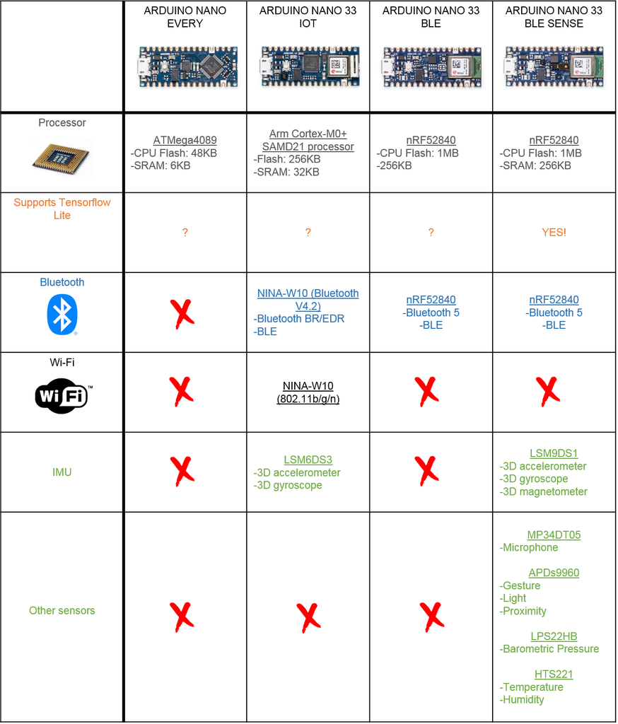
All of these boards are really interesting, but the only one that could be used for gesture recognition is the Arduino Nano 33 BLE SENSE board since it is the only one to have sensors and supporting Tensorflow Lite. Another interesting point is that Arduino Nano 33 IOT, BLE, and BLE SENSE boards have Bluetooth, so all of them can be used on the LED matrix to receive the BLE signals.
As you will see later, the codes I uploaded on the Arduino boards are based on many Arduino codes I found. So before starting, I decided to test these codes with the examples I found.
Step 2: The Glove (1/6) : Electronics


From step 2 to step 7, I use a scheme to help you understand better the process to make the glove. The highlighted part of the scheme corresponds to the part of the project described in the current step.
Concerning the circuit of the glove, it is very simple:
- The Arduino board;
- A 9V battery (I used a rechargeable 9V battery);
- An SPST switch.
Step 3: The Glove (2/6) : Case


The case is simply composed of two 3D printed parts:
- The first part in yellow contains the Arduino board, the battery, and the switch. I designed holes in this part so the battery can be charged and the Arduino board can be programmed without removing the lid;
- The second part in black (the lid) to protect the battery and the board.
I used a strip of hook-and-loop fasteners to attach this box on the hand.
Finally, I also designed a logo that I glued on the lid. It represents a cyclist viewed from the top, with 3 arrows (straight, left, right). The 4th arrow is detached from the others because bikes don't go backward.


Step 4: The Glove (3/6): Data Recording


Once the device ready, it was time to record data: the goal is to record all gestures many times. I set a threshold on the gyroscope, so when gyroscope values exceed this threshold, the Arduino board starts displaying the recorded data on the monitor.
These are the gestures I recorded:
- Arm pointing to the left (regular gesture for cyclists to indicate a turn to the left);
- Brake (gesture of the fingers to reach the brake);
- Hand back tilt;
- Hand front tilt;
- Hand left tilt;
- Hand right tilt.
Of course, you can add other gestures.
To record these data, I made a program that lights an LED of a different color every 20 movements. This way I know when to change gestures. I connected the Arduino board to my computer with the Arduino monitor open and placed my computer in my backpack.
Once all the gestures recorded, the last thing to do is to copy the data displayed on the monitor and save them in "csv" files (see the files uploaded on the next step).
Attachments

Step 5: The Glove (4/6): Training


For the training, I used this link and I just modified a few lines of code. Before starting the training, I'd encourage you to plot your data and make sure every movement is similar for one "csv" gesture file.
In "Upload data", upload all your files.
In "Graph Data (optional)", add one of your filenames:
filename = "Arm_left.csv"
Then modify this line to plot only the gyroscope data:
#index = range(1, len(df['aX']) + 1)
index = range(1, len(df['gX']) + 1)
Comment the following lines, so they look like this (again I don't use accelerometer data):
#plt.plot(index, df['aX'], 'g.', label='x', linestyle='solid', marker=',')
#plt.plot(index, df['aY'], 'b.', label='y', linestyle='solid', marker=',')
#plt.plot(index, df['aZ'], 'r.', label='z', linestyle='solid', marker=',')
#plt.title("Acceleration")
#plt.xlabel("Sample #")
#plt.ylabel("Acceleration (G)")
#plt.legend()
#plt.show()
In "Parse and prepare the data", add all the names you used for your data:
#GESTURES = ["punch", "flex",]
GESTURES = ["Arm_left", "Brake", "Hand_back-tilt", "Hand_front-tilt", "Hand_left-tilt", "Hand_right-tilt"]
And change also the samples per gesture if changed in the initial Arduino code:
#SAMPLES_PER_GESTURE = 119
SAMPLES_PER_GESTURE = 64
The last things to change is to comment the acceleration:
# normalize the input data, between 0 to 1:
# - acceleration is between: -4 to +4
# - gyroscope is between: -2000 to +2000
      tensor += [
          #(df['aX'][index] + 4) / 8,
          #(df['aY'][index] + 4) / 8,
          #(df['aZ'][index] + 4) / 8,
          (df['gX'][index] + 2000) / 4000,
          (df['gY'][index] + 2000) / 4000,
          (df['gZ'][index] + 2000) / 4000
      ]
Read and run every line of this page, and in the end, you can download the trained model.
Step 6: The Glove (5/6): Arduino Code

The final code I use on the smartglove is a mix of the following codes:
- "LED" example from the "ArduinoBLE" library (Peripheral>LED).
- "IMU_Classifier" found here: https://github.com/arduino/ArduinoTensorFlowLiteT...
I will not describe them since this Instructable would be way too long, but I encourage you to read the original codes for a better understanding.
Add your new model to the code, and you are ready to test it!
Step 7: The Glove (6/6): Test


As you can see on the video below, the LEDs light up differently according to the gesture recognized:
Step 8: The LED Panel (1/4): Electronics


As I said previously, I encountered several problems when uploading the LED sketch from the ArduinoBLE library on the Arduino Nano 33 board, and decided to use an ESP32 board instead. Therefore on the above pictures, you can see both boards.
Since both Arduino Nano 33 BLE SENSE and ESP32 boards communicate with 3.3V logic level, I added a quad-level shifter 3V to 5V (74AHCT125) to do the level shifting, as recommended by on the Adafruit Best practice guide.
I also added a 1000 microF capacitor to prevent the initial onrush of current from damaging the pixels.
And I made this circuit on a perfboard.
You can also see that I used both plugs of the powerbank, since I was afraid the LED matrix would require too much current. Therefore, the matrix and the microcontroller are powered with different outputs of the powerbank.
Step 9: The LED Panel (2/4): Case


For the LED panel, I wanted a modular case. Therefore the case is made with several parts (also because I have a tiny 3D printer), and I placed many holes to use screws easily.
To attach the panel, I used a strip of hook-and-loop fasteners once again.
You can download all the files I designed.
Attachments


Step 10: The LED Panel (3/4): Arduino Code


The final code is a mix of the following codes, after a few modifications:
- "BLE_Write" example from the "BLE ESP32 ARDUINO" library.
- "MatrixGFXDemo64" example from the "FastLED NeoMatrix" library.
Attachments
Step 11: The LED Panel (4/4): Test


And it is time to test it! Each time a gesture is recognized, a signal is sent to the LED panel and a pattern is displayed. You can also note that an LED lights up on the smartglove according to the gesture recognized.
In case you missed it, this is the video shown in the introduction:
Step 12: Final Test & Conclusion


Here is a video of the device when I ride my bike!
To conclude, I am very happy with this device. It helped me get much more confident with tinyML and BLE. Since then I also bought another Arduino Nano 33 IOT board, and I am currently doing a very exciting project with it that I will publish soon (don't miss it)! But there are also things that I would change if I ever do a second version:
- A better lid for the smartglove. The current one is just placed on the box, and stay fixed because it is tight. But during a ride, my hand hit an object and the lid fell and broke. So on the next version, I will probably use screws for the lid.
- A better case for the LED panel. I rapidly found out that the case I made lack easy access to the microcontroller USB port, in order to debug it or change its code, without having to unscrew the entire case. Also, the powerbank cannot be accessed and charged without removing the screws.
- More data for the training. A few times, some gestures are sometimes not recognized, and some are recognized instead of others. This is probably due to a lack of data (only 20 movements for each gesture). So more movements would make a better model and less error in gesture recognition.
It took me many months to make and write this instructable, so if it is not clear or a file is missing, please leave a comment below and I'll try to answer as best I can.
I hope you liked it, and see you soon for other exciting projects! :)

Second Prize in the
Arduino Contest 2020


