

Introduction: Breadboard Wires Modification M-M to M-F


A short instructable to share a tip.
Breadboard wires typically come in three various forms
- Male to Male
- Most common - these have a pin on each end
- Male to Female
- A pin on one end, socket on the other.
These are most useful for connecting up modules that you don't want to fix directly into a breadboard.
- A pin on one end, socket on the other.
- Female to Female
- Of the three - these are the least used in my projects
Breadboard Wires are cheap enough - but often I have found myself short of the correct type of wire for a project and cannot wait for a delivery.
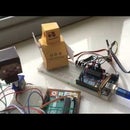
LCD Modules, Joysticks and ultrasonic modules like those pictured on this page are best connected using neat male to female wires.
This project shows how its possible to modify a common Male to Male breadboard wire to be a Male to Female wire with just a snip.
ps. Hope the photos are good enough, all taken with my mobile phone - no stock photos used in this instructable.
Step 1: Disassemble

Disassembly of the pin is done by carefully lifting the tag (1) up.. just the slightest...
And the connector will be released and easily come out in the direction shown (2).
Careful not to bend the plastic too much as it can easily deform or snap - we will need it intact for reassembly later.
Step 2: Make the Snip

Using a wire snips - cut off the pin at the point shown in the photo for this step.
There should now be a nice rectangular channel that a pin can slide into.
You can use the snips to gently shape the channel to make sure it looks just like photo.
Step 3: All Done!

Reassemble by sliding the plastic back on - making sure to have the tag the correct side up - and you are all done.
You now should have a cable suitable for hooking up those modules, or alternatively for combining with a male-to-male wire to make a longer wire.

![Tim's Mechanical Spider Leg [LU9685-20CU]](https://content.instructables.com/FFB/5R4I/LVKZ6G6R/FFB5R4ILVKZ6G6R.png?auto=webp&crop=1.2%3A1&frame=1&width=306)


