

Introduction: Build an Arduino


In this instructable I'm going to show you how to build an Arduino using an atmeg328 IC, I know that this sounds complicated but is quite easy to do. This project is if you need an arduino in your project but you don't want to use the arduino UNO or arduino nano. The atmega328 is the same IC you find in the arduino.
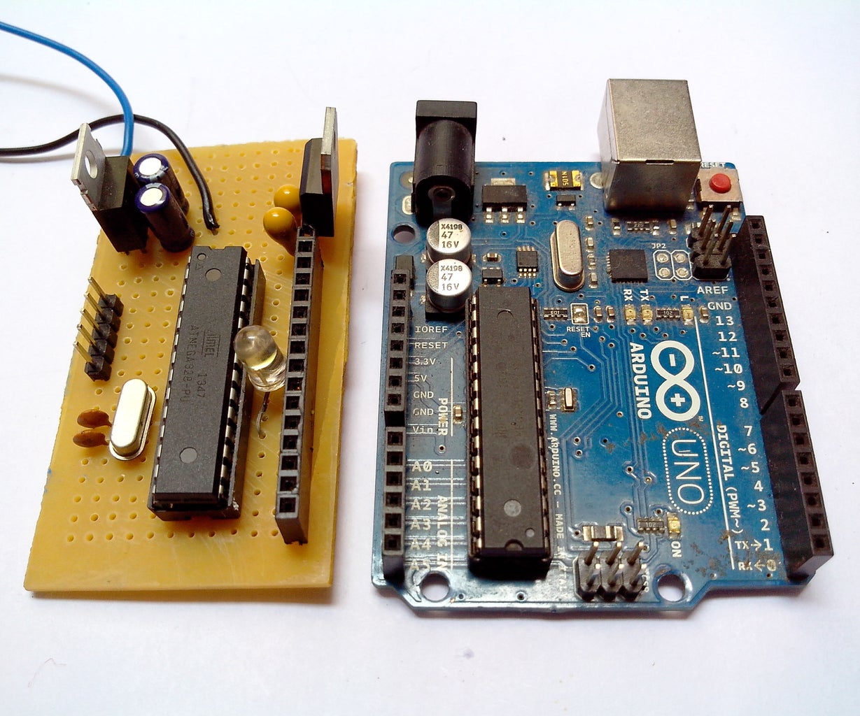
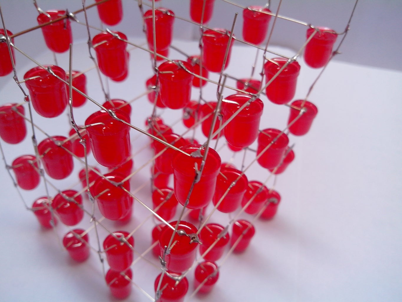
I built this because I made an led cube (I'll post it up soon) and i did not want to seal my Uno in a box.
Step 1: Tools and Components

As always lets start with getting all the components required.
Components
- ATmega 328
- 2x 10 uf electrolytic capacitor
- 2x 22 pf capacitors (ceramic disk)
- 7805 voltage regulator (5v)
- 16 MHz crystal oscillator
- Momentary push button switch
- LEDs
- 28 pin DIP IC socket
- LM1117T-3.3 voltage regulator(3.3v) (Optional)
- 2x 10 uf tantalum capacitors (Optional)
Tools
- Soldering Iron
- Multimeter
Step 2: Description

Once you got all the parts its time for assembling, I just want to say a few lines about atmega328. Well if you look at online stores for the IC you would probably see that there are two types of it one with boot-loader and the other without. If you spent some few extra dollars and brought the one with the boot-loader, you can skip a few steps in this instructable. If you brought the one without the boot-loader then you need to follow all the steps.
The boot-loader is necessary to write and upload codes from the arduino ide to the IC.
Step 3: Uploading a Bootloader


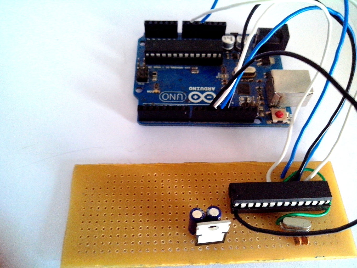
Here is how you upload a boot-loader to the ATmega IC. You would need an arduino UNO for this step. Follow the circuit as seen above and solder the parts on the pref-board, you don't have to connect the voltage regulators at this stage as the arduino would provide the necessary power.
First lest start with configuring our arduino UNO as ISP, this is done because you want the arduino to upload the sketch to the ATmega IC and not itself. Don't connect the ATmega IC while the below upload is running.
- Plug the arduino to a PC
- Open the arduino IDE
- Open > Examples > ArduinoISP
- Upload sketch
Step 4: Uploading a Bootloader2
With everything connected open the IDE from the folder you just created (the copy).
- Select Arduino328 from Tools > Board
- Select Arduino as ISP from Tools > Programmer
- Select Burn Bootloader
After a Successful burn you would get a "Done burning bootloader".
Step 5: Adding the 5V Regulator


After successfully burning the boot-loader lets complete the arduino. Adding the 5v regulator is an important part of the circuit, for the voltage regulator I used a l7805 IC which is commonly found on the internet. With the printed side of the IC facing you and the legs facing down the one to your extreme left is the input. The one in the center is ground and the one to you extreme right is the output.
Follow the circuit and connect the voltage regulator to the arduino.
Step 6: 3.3V Voltage Regulator


This is optional and not really required this just to power the external shields and modules that require a 3.3V power supply. The arduino just requires the 5V power supply.
Step 7: First Code

Once you have completed all of the above steps you now have an working arduino. Now time to upload your first code. To upload the code you just remove the ATmega 328 from the UNO and replace it with the new IC. Once you have done uploading the code replace it back.
And now I had my arduino which went into the led cube box (I'll leave a link here once its done).


