

Introduction: CNC Pendant


One of the things about building your own CNC is the joy of discovering everything that you can add to it to make your workflow better. In my case, the first was a touch probe. This makes setting zero height on your work-piece so much easier than using the "paper feeler gauge" method. Right up until you are holding the probe base in place and then reaching over to the mouse/keyboard to trigger the probe routine. It can be like a game of Twister in your workshop. Then there's all that jogging, zeroing, homing, panic stopping, unlocking and resetting. The answer is a pendant. There are a gazillion projects on the internet on how to build these, and here's my contribution.
My CNC is a home build, own design, and made using not the cheapest parts.
40x40mm profile extrusion, 15mm acrylic sheet..hence the name "TransparentCNC", 1605 ballscrews, HGR20 rails and guides, Nema23 4 axis stepper kit with TB6600 drivers driven by an Arduino Uno with the Protoneer CNC shield on top. Seemingly a million cap screws and t-slot nuts, etc and all up I'm probably in the region of $2k, but don't regret any of it.
For software, I'm using sketchup for the CAD, and f-engrave or Estlcam for CAM. I really like Estlcam for a low cost and very easy to use CAM package. And finally, UGS for running the machine.
One part I used in this project was the left side controls of a NES gamepad (good old 'dogbone' controller). Now I could have shortcut the whole project by using just that and swapping the existing chip with the Pro Micro. This uses the same chip as the Leonardo, but much smaller package. The Leonardo/Micro is a HID capable chip, so it can pretend to be a mouse and/or keyboard. But I wanted an LCD display, so a custom enclosure and loads of complication is called for.
Supplies
Shopping list:
- 1 x Arduino Pro Micro (available still in the older USB-D connector, or the newer micro USB)
- 1 x USB cable, long enough to stand at the CNC and reach the computer, and the right connector for the Arduino
- 1 x NES game controller, you are going to chop this up, so don't use your favourite one.
- 1 x 5mm tactile switch (for a reset button)
- 1 x 1602 LCD unit with the I2c backpack
- 6 x momentary switches
- 3 x 20mm brass standoffs (for attaching the back and front enclosure halves)
- 6 x M3 screws + flat washers to go with the standoffs
- Qty wires (or length of computer ribbon cable)
- 12 and 18mm thick MDF (A4 size piece of each will be enough) - Only if you are going to CNC the enclosure halves. Ignore this if planning to 3D print.
Tools:
- Soldering iron with a small tip,
- Solder
- Sandpaper for finishing the MDF parts
- Some sort of sealant for the MDF (polyurethane or paint spray)
- Drill and drill bits.
- Current CNC or 3D printer for the enclosure
Step 1: Electricals Layout


As seen in the fritzig image, the wiring is really straight forward. The button ground loops (main buttons and jog buttons) allow the buttons to pull the connected pins low when pressed. The LCD backpack uses a dedicated ground connector to avoid any issues with button bounce.
The only real current load in the Arduino is the LCD screen, and it can handle that with ease.
Now you might think only having 6 buttons is a bit limiting, however, the trick is in the sketch used.
The sketch uses the 'ClickButton' library. This allows up to 6 functions per button depending on how you press the button. Single press, double-press, triple-press, single-press+hold, double-press+hold and triple-press+hold can all be given different responses.
In my case, I used the top 3 buttons as X/Y/Z axis select (single), cycle jog step size values (double) and zero (press+hold)
The bottom 3 are probe, move and connection 'zones' (for want of a better word)
- Probe: Initiate probe (single), stop probe (double)
- Move: Move Z up 10 (single), Home X/Y (double), STOP! (press+hold)
- Conn: Connect/disconnect, Unlock, Soft reset
On the NES buttons, I use the same up/down to move the Y and Z axis except Z needs a double press.
The default debounce options in the library config make it pretty reliable and not sending incorrect values. Note that UGS does not have a hotkey option to trigger the probe cycle. This requires a macro to be created named and saved, then assign a hotkey to the macro name in the keymapping config.
Here's mine (grbl 1.1h):
G10 L20 P1 Z0;G90 G21;G21 G91 G49;G38.2 Z-20 F250;G90 G21;G91 G21 G0 Z5.0;G90 G21;G21 G91 G49;G38.2 Z-20 F150;G90 G21;G90 G21 G0 Z0.0;G90 G21;G10 L20 P1 Z16.15;G90 G21;G0 Z10
Note the value "16.15". This is the height of my probe block, so adjust to suit yours. Mine is one of the slugs cut out of the 15mm acrylic for a stepper motor, hollowed out and houses an LED, cable going back to the CNC shield and a short lead for the aligator clip. It's topped off with a steel fender washer as the contact point, similar to what is shown in the shameless snip of someones image. The LED is a nice way to know if your contacts are working before you slam the bit into the top of the probe.
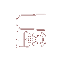
Step 2: The Enclosure

I've attached a DXF of the design for mine, and feel free to use it or anything else you like. Just make sure the holes are the right size for your buttons. I used ones requiring a 16mm hole.
Once the body is made, do a dry-fit test and make sure everything sits nicely in the right place. I CNC'd mine and once I was happy with the fit, gave it a couple of coats of satin clearcoat.
Place all the hardware inside then solder up the connections. For the Arduino, I surface soldered the wires to the header pin pads. I locked the button nuts, wiring, arduino and NES button assembly in place with hotmelt glue.
Now I would include a photo of the inside of mine, except it is a horrible mess from where I had to rip half it back out again when I bricked the arduino with a bad sketch change. (lesson identified..hopefully learned) I was able to recover the arduino after much messing about with Arduino as ISP, but I'm not proud of how it looks on the inside..even though it works fine.
I added a small tactile button which fits in the recess at the top of the unit and requires a determined effort (corner of fingernail or nail/pin) to activate. It's not a button you want to accidentally hit, hence it is recessed. Useful if the controller loses contact with the computer, or you have a sketch change error. Pressing and holding this immediately after clicking upload for the sketch can get you back from what appears to be a bricked arduino.
Also note: If you are using the board with the micro USB, be very gentle! I successfully removed the USB plug connector on 3 boards because of rough handling and they are only attached by 2 small solder pads on the board. So be warned
Attachments
Step 3: The Jogger Control


I had thought about using a rotary encoder, but I had been experimenting with a wireless PS2 controller and really liked the left side controls. Since I didn't really want to destroy the PS2 controller, I bought a new NES USB one off our local version of ebay (TradeMe) $5 + $6 for postage..job done! And what do we always do with new things?..take it apart.
The key to making this work is:
- Fully disassemble the thing,
- Cut out a big enough circle for the face,
- Ensure you have enough of the circuitboard cut off to clean off some masking and expose the traces to solder wires to without impeding the action of the main knob.
You will find a main common trace that is connected to all 4 pads, then a trace for each. Solder a wire, should have 5 total. Don't worry too much about which wire goes where between the pad and the arduino, except for the ground..that needs to connect to the ground loop (obviously). If they are wrong, then you can simply change the pin assignment numbers in software.
I found that a couple of small drops of superglue on the mount tabs of the silicone pad helped keep everything aligned during reassembly. So your stack should be:
- Circuitboard
- Silicone button pad,
- Button,
- Faceplate
Hotglue to the rescue again to stick the layers together around the outside only. You do not want glue to get inside as it will inhibit the button action or prevent a pad from making contact. Glue and test..then retest.
Step 4: Code, Close and Config

I've attached the sketch as it is currently configured. The function to update the LCD screen is still a work in progress and very much dictated by what functions you apply to the buttons, and how you want that displayed on the available space. I've left mine in as an example...maybe.
UPDATE: I've updated the sketch (as of 28 Jan) to include a timer to return the LCD to startup state, and removed extraneous keyboard.begin lines and general housekeeping.
You'll also note that each active button action produces some serial output. I highly recommend that you make sure that each button is producing some form of output (not worrying too much if it is correctly assigned, just that the pins are being triggered). This is a sanity check that your soldering is OK, and you haven't created any bridges and triggering multiple action with one button. If you are happy that the buttons are triggering, then you can remove these lines. This current sketch used about 58% of the Micro memory..so not a problem to leave it in.
To close up the enclosure, pick 3 or 4 aesthetically pleasing points around the edge, ensuring they are in an area that will allow a drill to pass right through, and drill a 3mm hole from front to back..or back to front...whichever works for you. Attach a 20mm standoff with the appropriately sized screw in each of the holes, and they will marry up with the holes drilled in the opposite face, providing something to screw the 2 halves together. The photo is about as detailed as I dare without showing how ugly the inside is..but you get the general idea.
The sketch itself is pretty self explanatory:
- Set up an array of buttons,
- Assign each button to an arduino pin,
- Update the status of the buttons (first statement in the loop section)
- If the button state matches a given condition, execute the function or instructions listed.
It's now your choice as to what shortcuts you want to use.
Go into UGS Tools->Options->Keymap, and assign some shortcuts to the actions you want to run from the pendant, then replicate those in the button action sections. For example, I assigned CTRL+1 to zero the X axis, therefore in the sketch on a press+hold ("case -1") for button 1, calls a function "shortcut_ZERO_X()" which is:
void shortcut_ZERO_X()
Keyboard.press(KEY_LEFT_CTRL);
Keyboard.press('1');
delay(100);
Keyboard.releaseAll();
}
Don't forget the releaseAll call, else the keys will be forever held until the pendant is rebooted or reset.
Tip: If your pendant is in build state that will allow you to attach it to your CNC computer, then when it comes to entering the keys for an action, just press the button. It will type what you set in the sketch. Much easier than writing it down or trying to remember what you set, and even easier to change if you don’t like the assignment.
Attachments

Step 5: In Closing
I had not intended to document the project with an instructable in mind, so it's not as well photographed or staged as is expected from a good quality instructable, and for that I apologise. However it was such a fun thing with some good learning experiences that I wanted to share. As I said at the start, there are a lot of "DIY pendant" stories out there so I'm under no illusion that what I made was 'freakin awesome!' or groundbreaking, rather just another solution that CNC peeps can use...or not.
A lot of credit goes to Erik de Ruiter, being the inspiration and basis of this project.


