

Introduction: MDF CNC Machined Retro-style Arcade Cabinet


I was contacted some months ago now, by a Swedish gentleman, with a request to design a retro-style arcade cabinet to be used as a housing for a desktop computer - and jumped at the opportunity to further my CAD design skills. I was given some reference materials at the start of the project, but there were a lot of specific requirements so the project was mostly done from scratch. So, I hopped into Fusion 360 in order to bring this idea to fruition.
Supplies
18mm melamine coated MDF (1.5 x full sheets)
5mm clear plexiglas / acrylic
Bambulab X1C 3D printer (for some brackets and bits and bobs) w/ Bambu PETG basic filament
Woodscrews / machine screws / nuts to fasten everything together (from Spax for the woodscrews and Accu for the rest of it)
Step 1: Humble Beginnings

Firstly, I decided on the base dimensions that would make up both side panels. These were fairly critical as they would dictate the dimensions of most of the other pieces. I took into account things that would be stored (eg a keyboard in one section) and any other brackets etc that may have to be later added. All post-processing operations (eg fillets) were done once the sketch had been extruded rather than in the sketch itself.
Step 2: Getting in the (material) Groove

With fillets having been added where necessary, and the model extruded 18mm to match the thickness of what was going to be the melamine coated MDF, sketches were added for material grooves - the idea was that crossmembers (one for mounting a monitor support bar, one to fit plexiglas for covering said monitor, and some others for various aesthetic reasons).
The grooves were made with centre-to-centre slots, mostly, or rectangles, extruded, with fillets added afterwards.
Step 3: Fan Mounts, Holes, and a Cheerful Smattering of Features


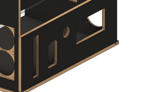
Now this is starting to take some shape! It was requested that some mounts for 280mm radiators and 4x140mm fan mounts (on top) be added, as I was told that this cabinet would make up the housing for a watercooled system.
Image 1: 280mm radiator mount added, with plenty of clearance on the outside, done with rectangles, extrudes, fillets, and the 'hole' tool.
Image 2: Here's what the cabinet has come to so far, most of the panels have been added, as well as some fan mounts on top. The thinner bit of Plexiglas on top is reflective of the similar 'Marquee' areas of retro arcade cabinets, and I was advised that it would be painted to match the intended style.
Image 3: Some 5mm clearance holes added, to allow the 4x40 Spax MDF woodscrews to go through into the crossmembers easily.
Step 4: Mirror, Mirror, on the Wall

I realised, probably far too late, that the left side panel was to be identical to the right one! So, it was a fairly quick job to create a plane exactly in the middle of one of the crossmembers, and mirror the right side panel across to the left. A very useful tool to use if you haven't yet familiarised yourself with it.
Step 5: Back to the Future


It was time to add something for this cabinet to sit on, and something to stop dust from entering at the back!
The model bottom was a fairly simple job, with slightly oversized dados (18.2mm for the 18mm MDF) used, as with all the grooves for the crossmembers. Though, had I done this again, I would have used glue-only rabbets as that part did not fare as well as I would have liked in shipping.
In terms of the back, for now I left the back panel in two parts, a fixed one (lower, pictured in the first image) and a moving one (more on that later). Given that a computer was to be used inside this, I needed to design mounts for an ATX powersupply, a cavity for the open benchtable case being used, among other features such as a cable guide, and a space for a Keystone panel.
Step 6: 3D Glasses On


Now's when 3D printing gets involved, and it gets really fun. For the back panel (top) to be lifted in and out, I decided to 3D print some grooves out of PETG. It was my first time with the material, so I was very relieved that it went well and that the Bambu X1C handled it like a champ!
I was also asked to 3D print a little mount for a small touchscreen monitor that would display weather data and similar. While I probably could make a whole instructable for this, it was nothing new in terms of features, just importing a manufacturer CAD file, placing holes appropriately, and a few sketches and extrudes. That was also done out of the same black PETG (Bambu PETG basic); I found the finish to be very pleasing on this.
Step 7: Milling Around


Unfortunately, many of the pieces were far too big for my little CNC router. Less unfortunately, I was able to find Riz, of East London CNC, who was willing to take on what ended up being quite a big project. The folks at ELCNC were able to handle all the materials before I picked up the final product which helped a lot, as I'm not sure I would have been able to fit a full 8'x4' sheet in my space! Pictured are some of the images that Riz kindly took from the process, showing the lovely finish from the pearl black melamine coated MDF that was sourced. Here's where I started to get *really* excited about what the final product would look like!
Step 8: Should Have Hit the Gym

Here it is, almost all assembled next to the 3D printer! My sheer excitement at having this almost completed was only tainted by the intense muscle fatigue: hauling large, thick, fragile pieces of MDF turned out to be an arduous exercise, making me regret my sitting hunched over a laptop on Fusion where some physical exercise may have been more beneficial!
Step 9: We Have Ikea at Home


Following months of on-and-off CAD and logistical work to get this project through the door, it's safe to say that I was hugely nervous about actually shipping this stuff from the UK to continental Europe. Fortunately, the pieces arrived largely unscathed, and the cabinet was assembled in its new home shortly. The first picture shows the cabinet in a state of half-assembly (I shall update this when more images come through). I am advised that it is to be painted, which I am very excited to see!
Step 10: So What Have We Learned
Goodness, this has been quite a lot of fun to write I must say. It's my first time documenting the process in such detail, and I can certainly attest to the fact that it's made me really think about the whole thing. I'll put my hands up and say that all the CAD images were from the MK2 file that was made, where I chose to name all the sketches and components, instead of in the MK1 version where serious crimes against the gods of CAD were committed. So, especially when working on larger projects such as this...
- Make sure to fully define and name all your sketches, it'll make your life easier in the future
- The move tool is your enemy - down the line you will not really find it easy to edit the sketches etc involved. It's much better to leave everything in place and create a separate assembly (or create the component in place).
- Project geometry is good until it isn't - it's easier to sketch things again having projected them rather than creating features based on projections. Should those projections ever change, you will certainly find yourself facing issues there.
- Create components not bodies - it's easier if you want to individually export components, especially when outsourcing manufacturing
- Take breaks - seems obvious, but after 2h+ straight I found that I was largely unable to concentrate and I made mistakes that would hurt me down the line. This is a more basic point, but an important one nonetheless.
SO, I hope through what ended up becoming a bit of a ramble, you managed to follow the process along with me, and take something from this. I'll try to respond to comments here, I'm also active on the Fusion students discord if anyone wants to ping me @aquacustoms over there.
Participated in the
Arcade Student Design Challenge


