

Introduction: Carving 3D Terrain Topographic Relief Maps on a CNC Machine by Steve M. Potter


I will describe in detail my process of taking satellite terrain imaging data and turning it into a CNC-carved work of art.
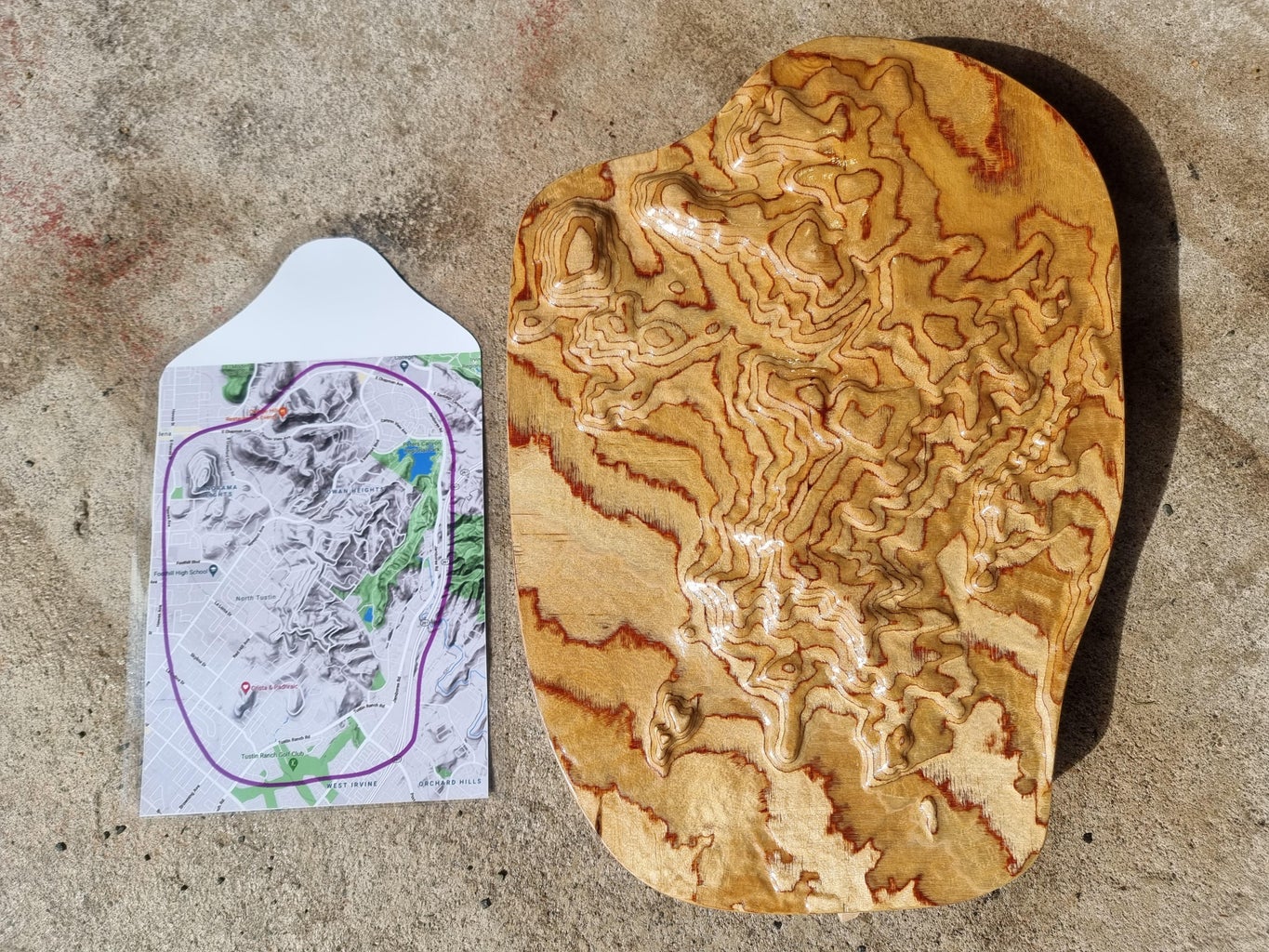
The result can be a lasting heirloom that can also be educational or of great personal significance to someone who has lived on or trekked across the area represented.
WARNING: THIS IS NOT EASY
When all goes well, the whole process takes about a week.
To accompany this Instructable, I made a YouTube video. This is for those who prefer talking and images rather than printed words. It has some more details and captions than the images I included in this Instructable. Find it on my YouTube channel, professorstevepotter.
NOTE: there are a lot more images in this Instructable than those shown in thumbnail form. Be sure to click on the "5 more images" buttons to see them all. If you want to see some videos of the CNC carving process and even more photos of the Making Of one of my works of art, here is a Google Photos album I put together: https://photos.app.goo.gl/p1RgX2D5QbDBSv2MA . Be sure to click on the i with a circle around it to see the captions (or scroll up, if viewing on your phone).
Briefly, here are the steps:
- Figure out what location to carve. Where, how big, how much terrain.
- Get the wood ready. Expect to put lots of work into shopping for quality wood and getting it home safely, cutting to size, and possibly gluing layers.
- Create a 3D model (STL file) of the desired region using TouchTerrain. This amazing tool is what makes this tutorial’s approach much easier than others I have come across (Appendix 2).
- Import the 3D model into a CAM program to generate toolpaths. Many steps here. I use VcarvePro, but many other CAM software packages, such as Fusion360, can be used.
- Fix the stock to the CNC machine and use the toolpath g-code to carve it! Expect some very long cutting operations (many hours). I use my homemade Portable Primo MPCNC (Mostly-Printed CNC). I modified it to speed it up.
- Sand the carved artwork. Laborious, unless the carving was done with a very fine stepover. Because these carvings are so tactile, you should not skimp on the sanding.
- Finish the sanded artwork with lacquer. Usually about 3-6 coats of lacquer, with some sanding in between. Several days’ work. You could leave it unfinished, but many unique features of the wood grain will only show up after sanding and finishing.
- Add final touches, such as resin oceans or lakes, branding, text, a printed map on the back, a frame, hanging/mounting hardware, packaging and mailing, or hanging it on the wall.
- Congratulate yourself if you made it to the finished carving!!
Go to my YouTube video tutorial...
Supplies


Tools and Materials
- A CNC machine. Even a cheap one will do for a small piece. I use the Mostly Printed CNC Primo by V1 Engineering, which I built and upgraded myself for about $1000, but you could get one finished for as little as $600. I highly recommend this design if you like building and hacking things. The performance/price ratio of the MPCNC is better than ANY other CNC machine.
- CNC bits: 1. a long ¼” (6 mm) endmill for roughing and for cutting out the piece. (Alternatively, a shorter bit for the roughing.) 2. A fine ball-nosed bit 1-2 mm diameter at the tip (1/16”), ideally a long tapered one.
- Computer with a good amount of RAM and CAD/CAM software such as Fusion360 or VcarvePro.
- Wood. I prefer to use Baltic birch plywood of high quality.
- Lots of small wood clamps with screw adjustments.
- Gorilla wood glue.
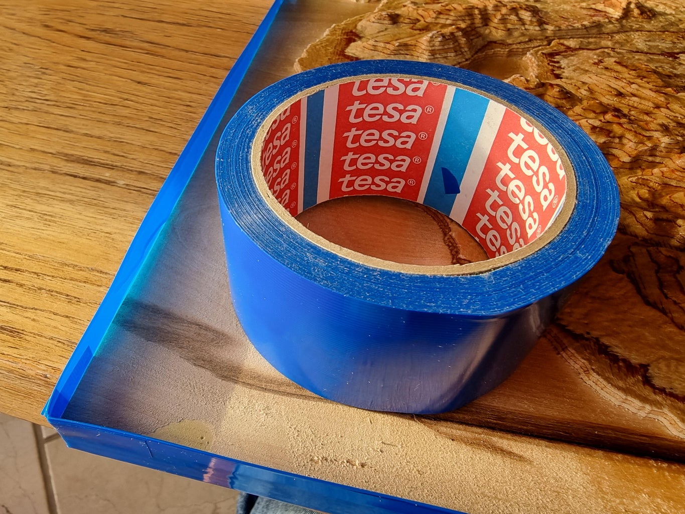
- Tape to hold down the workpiece. I recommend TESA 4298 strapping tape and strong, thin double-stick tape (Not foam. Permanent, not “repositionable” or “removable”).
- Quality sandpaper of grits from 100 to 400.
- Belt sander.
- Bandsaw, jigsaw, scroll saw, or coping saw.
- Dremel or similar motorized hand tool.
- Abrasive sponge bits for the Dremel.
- Air compressor or spray duster.
- Personal protective equipment: Dust mask, goggles or safety glasses or face shield, ear protectors or earplugs. A dust extraction system would be nice. I use a shop vac.
- Quality spray varnish. I prefer gloss.
- Printer, quality paper, laminator, and lamination film (if you wish to print a map to go with the carving).
- Molding, miter saw, and CA (cyanoacrylate) glue if you wish to make a frame.
Step 1: Decide on Your Project Goals
This tutorial is based on my own experiences with computerized woodworking. I make digital terrain carvings (3D relief maps) of places I have lived, or for friends' and relatives’ favorite places. It is not oriented toward 3D printing of terrain, though the early steps can be used for that. Carvings can be made from other materials than plywood, but that is what I will focus on because I love the way it comes out. Other materials I have seen people use for terrain carvings include:
- Thin pieces of contrasting wood laminated by hand
- Colored paper glued and pressed into a block.
- Plastic, such as Delrin
- Richlite phenolic resin-infused paper
- Metal
- Dense foam
Where is the terrain you wish to carve? The US has the most freely available image data, so if your desired region is in the continental US, you will have more high-resolution options. In addition to terrain from Earth, you may also carve terrain that NASA has mapped on the moon or other planets or their moons. My father, Philip D. Potter, helped to design the side-looking radar they used for this (he was an antenna expert at their Jet Propulsion Lab). JPL.nasa.gov is a good place to start to see what is available.
How big of a region do you wish to carve? This will affect some practical matters, such as what resolution of imaging data you need, how many tiles of imaging data you will need, and whether you will need to exaggerate the vertical scale of the carving. If you are zooming in on a region that is only a few tens of km across, then you will need 1-arc second data or better, or you will miss many small features of the terrain. If you are zooming out to produce a carving of a region that is hundreds or thousands of km across, then it is easier to deal with lower-resolution image data. The files won’t be so huge and you won’t need to eventually throw away most of the data before doing the carving.
What are the exact borders of the region you wish to carve? Can it be rectangular, or should it be some other shape, such as the outline of a state, island, mountain range, or country?
What level of quality do you require? If you want a top-quality carving, i.e., one you could sell or display in a gallery, you will need to make a lot of practice ones, to get a feel for what is possible and develop the skills and intuitions you will need. I say this to set your expectations that the first carving, and perhaps the first few carvings, are likely to be disappointing. My best first-off carvings all took over a week of effort to design and make. The good news is that with CNC, it is likely that if you have a good process, it can be repeated to produce additional nearly identical carvings in substantially less time than the first one. I hope this tutorial will save you much of the trial and error that I went through.
Step 2: Prepare the Stock


Before getting involved with the computer side of things, get a plywood blank (AKA the “material”, “stock” or “workpiece”) ready to carve. Get some nice expensive Baltic birch plywood, the best you can find. I use 18 mm Baltic birch plywood. Marine-grade birch plywood here in Ireland is pretty good. Regular birch plywood has thinner plies and more voids. In 2022, Baltic birch costs about 190 euros for a 4’ x 8’ x 18 mm sheet (yes, most sheet stock is still cut in feet even in countries like Ireland that use the metric system). It should have all knots removed and patched at all layers, not just the surface. If you see any defects, or worse, holes (voids) on the cut edges in the shop, don’t buy it. The stack in the photo is pretty good with only a few knots, rated BB. Grade A would be better. One layer with a hole in it can (SURPRISE!) ruin your efforts. Peaks may break off. You can’t see them until you are well into the carving. Inspect the cut edges carefully. Cheap plywood will also have overlapping layers. If you are just practicing or starting out in CNC, go ahead and use cheap plywood until you have the details worked out.
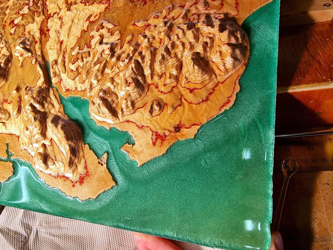
The glue in between plies is reddish-brown and provides some nice effects when carving terrain. One of these is that it can look just like the contour lines on a topographical map. Baltic birch with these red layers is the stuff that Martin Molin used for the Marble Machine X.
A YouTuber (Proun Goods) made his own plywood out of alternating oak and walnut, a few millimeters thick each. That is one way to ensure you know what is in the middle of the stock. It produced a nice effect with the terrain carving he did. But that requires laborious bandsawing, planing, and sanding to get flat slices to glue together well.
Make sure to get a flat piece of plywood. It should not be the one on the top of a stack, but the second or third one. That is because the one on top will have two different moisture situations on its top and bottom faces. It may look fine in the shop, but a few hours after bringing it home, it looks like a Pringle.
Cut out the properly sized piece with your table saw, bandsaw or jigsaw. Use a fine-tooth blade and cut slowly to avoid tear-out (splinters). If there is tear-out, sand it off so the workpiece will rest flat on the spoilboard. I like to glue two layers of 18 mm plywood together to provide a nice heft and lots of scope for the terrain surface to pass through many layers. I use Gorilla Glue wood glue or Titebond Ultra III. The latter makes a darker layer you may wish to avoid. Test your glue first on a scrap piece, and, after drying, cut and sand it at angles to see how the glued join looks.
Sand or plane off any splinters or high spots before gluing. Apply lots of glue to both faces and put as many clamps on as you can afford. MTMWood uses pneumatic and hydraulic presses to glue his flat pieces. It may help to sprinkle a bit of salt on the glue of one side, which will prevent the two pieces from sliding against each other as you put the first couple of clamps on. If you don’t use enough glue or don’t clamp well, you run the risk of having your favorite mountain fly off the CNC halfway through the carving process. Put waste boards between the clamps and your stock if you don’t want clamp marks on the back of your finished piece. (The front/top will be carved, so clamp marks will be gone) Tighten the clamps very tight. There should be squeeze-out, so put down a drop cloth or something to catch glue drips. If you don’t see glue squeezing out all along the seam after tightening, break it open and add more glue, after looking carefully to see where it is needed.
After the glue is dry, measure the thickness of the glued stock with calipers, and the overall size with a ruler. You should enter these dimensions into VcarvePro later when setting up the job.
If you are trying to use wood that is not very flat, such as a dried tree slab, you can fasten it down lightly at the edges in such a way that it does not rock (but without putting any stress on the wood that might flex it), face it on the CNC, sand and vacuum the faced surface if needed, apply blue TESA tape and double-stick tape so that its flat, faced surface is in good contact with the spoilboard and very well adhered. Stand on it to be sure it is well-stuck. Then face the other surface to provide a level top to start with. Now measure and record the thickness of the workpiece from face to face.
Step 3: Obtain the STL Model of the Terrain


My earlier versions of this tutorial (and others like it on the internet) had pages and pages of complicated resources and procedures to find 3D terrain data (GeoTiffs or grayscale height maps) and convert them into a 3D model suitable for carving. (See Appendix 1, Stuff I do NOT recommend) This whole process got much easier thanks to TouchTerrain, created by Profs. Chris Harding of Iowa State U. and Franek Hasiuk of the Kansas Geological Survey at the U. of Kansas. Their students print terrain models with 3D printers to help them learn geology. With TouchTerrain’s fairly simple web interface, you select the region you wish to carve and specify the details of the model. It crunches the image data and gives you an STL file to download (or an OBJ file if you prefer). Best of all, it is free and open-source!
Some background about terrain datasets
There are many (too many) sources for digital heightmap (Digital Elevation Model or DEM, also called GeoTiffs) imagery. They have pluses and minuses, so get to know your data. The best (free DEM) in the continental US is 3DEP from the USGS. And for coverage of the entire globe, the JAXA dataset AW3D30. The greyscale of a GeoTiff represents altitude, white being peaks and black being sea level. (There are even sea floor maps: bathymetric heightmaps.) The files are usually 16-bit TIFFs, and most of the data is compressed all to one side of the brightness range so don’t panic if it looks blank. Pay attention to when the data were collected, if the terrain is changing, for example, Mt. Saint Helens before and after it blew its top.
Using TouchTerrain
This tool is far easier to use and more powerful than any other I have found, for collecting terrain imagery and turning it into a 3D model that can be carved. In fact, the time saved by using TouchTerrain is why I felt compelled to write this tutorial, even though other good tutorials are out there (see Appendix 2). The user interface at https://touchterrain.geol.iastate.edu/ is pretty self-explanatory, but if you need help, hover over the question marks. Here is my TouchTerrain workflow in detail:
- Type some geographical location into the search box. If Google Maps can find it, this will too, since it is using Google’s search tools behind the scenes.
- Choose an Elevation Data source. I recommend AW3D30 made by JAXA, or if your area is in the continental US, USGS/3DEP/10m (from NASA).
- Zoom in or out so the features you value are showing. Drag the Transparency left or right to switch between a map with roads and shaded terrain. If you don’t see any shaded terrain, you need to select a different Elevation Data source in the pull-down menu. All the tools in the topmost box won’t affect your carving except the data source. They are there to allow you to make a nice hill-shade image of your mapped area.
- Click Re-center box on map to move the red rectangle to where you are, and grab the corners or edges to move them to exactly where you want them. Now is a good time to consider the desired aspect ratio (W/H) of your final artwork, and take into account your machine’s work area and the stock you have.
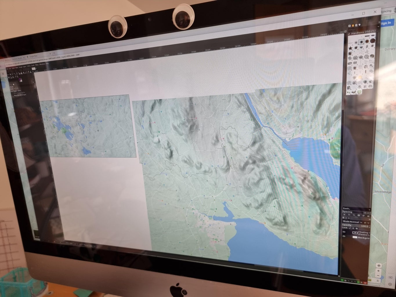
- When you have things where you want them, open the Area Selection Box pane to reveal the latitude and longitude of the selection. Take a screenshot of this and the map, perhaps with a few different hillshade options, so later on you can make a printout to go with the carving. North sun direction and steep (55 degr.) gives very good contrast for shallow features, better than Flat. Note that on the map, you can choose Map or Satellite for the background that is faded in and out with the Transparency slider. I sometimes save the Map, Satellite and 0% transparency hillshade separately and combine them with Layers in Photoshop, where you have more options for how to merge/overlay images.
- There is an option to use a polygon that you created (e.g., using Google Earth KML file) instead of a rectangle, as your selected outline. That may be helpful for creating a model in the shape of a state or country, like I did for the Idaho carving.
- In the 3D Printer Options pane, see the notes in the “CNC?” popup. I suggest you choose the best resolution you can get away with. Pick a size that fits what you hope to carve. If you want a carving larger than 20cm, you can either scale the model up (see below) or use tiles to increase the extent of the model. Each tile will be its own STL file. (Remember, this tool was created for 3D printers with fairly small print beds.)
- Keep an eye on the Effective DEM resolution it calculates, in meters. This is the smallest possible feature size you will see in your carving, assuming you carve the model at the size TouchTerrain gives you. If you plan to scale the model up to a bigger size, you may wish to ignore the “yellow box” warning, as oversampling probably does not apply to you.
- Set the Model Base Thickness to its max, 5mm, unless you want a thin base for some reason.
- Vertical Exaggeration depends very much on the extent (X and Y) and altitude (Z) of the terrain you are going to carve. The Earth, when scaled down to the size of a ball bearing, is much smoother than a ball bearing. So for bigger extents, you will generally use a larger Z factor. I typically use x3 for a region that is 50-100km across, but the mountains are not very tall in Ireland. You can change this Z factor later in the CAM software, so don’t stress too much about getting it right here.
- Choose STL binary format.
- In Manual Settings, you can enter command line modifications to the model. You can learn more about the possibilities in the ReadMe.md on Chris Harding’s TouchTerrain Github repository: https://github.com/ChHarding/TouchTerrain_for_CAGEO. I use the “lower_leq”:(0,3) option to create a 3 mm cliff around the shoreline down to the seabed, for filling with resin (see below). Unfortunately, any on-land features that are also at 0 feet above sea level will also be lowered, causing deep holes in your model there too. TouchTerrain will put a GeoTiff (16-bit greyscale height map) in the .zip file you download that may be used to fill in the 0 ft MSL features of your model, but that is an advanced topic I won’t cover. Here is what it says in Github: “lower_leq”: default: null. An alternative to ignore_leq. Given a list in the format [threshold, offset], all cells less than or equal to 'threshold' will be lowered by the offset. This helps with giving emphasis to coastlines. The offset is in mm with respect to the final mesh size. Unaffected by Z scale.
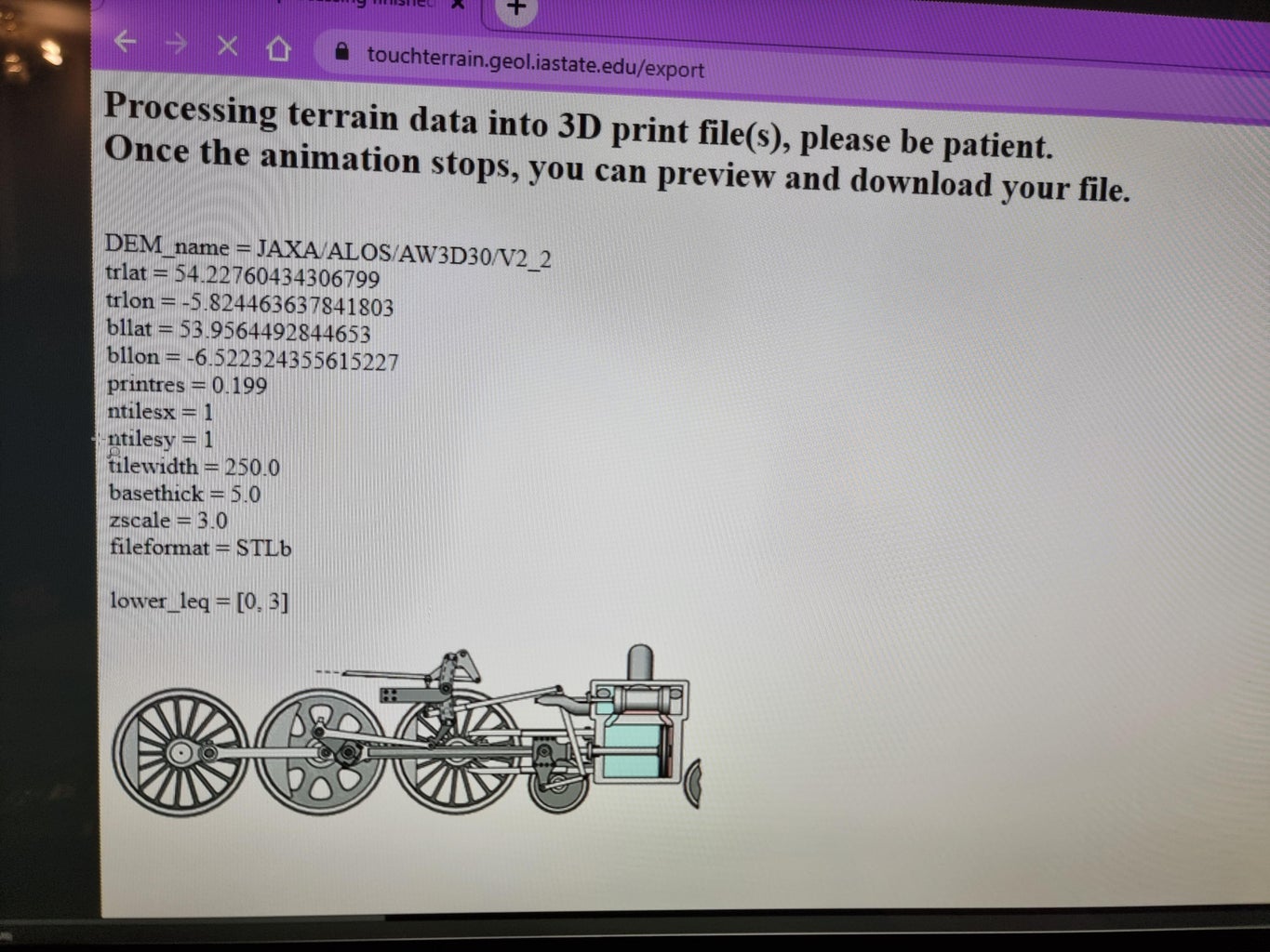
- Click Export Selected Area and Download File. You will be sent to a new page with the parameters you have chosen, and an animation of a locomotive mechanism turning the train’s wheels. It may take 5 minutes to crunch the numbers. If it says “Your model is too big!” then you have to go back to the previous page and tweak the parameters to reduce the resolution or the extent of the model. For a more powerful way to use TouchTerrain, you have a couple of options: install the Standalone on your own machine, which I have not tried. See the ReadMe.md on TouchTerrain's Github repository. Chris Harding has set up new (Nov. 2022) option: to run TouchTerrain on Google's Colab with processing in the cloud. This requires some proficiency with python, but the instructions and steps are pretty clear. Here is the link: http://colab.research.google.com/github/ChHarding/TouchTerrain_for_CAGEO/blob/master/TouchTerrain_jupyter_starters_colab.ipynb
- Once it is finished, you will see a box to tell the creators what you are using it for. Please FILL THIS OUT! If more people say they are doing CNC instead of 3D prints, the coders will add more features for us, or maybe increase the max number of pixels (currently at 700kpixels).
- You may preview the model in your browser, but since this takes a while, I suggest just downloading the .zip file and previewing it on your machine. I use PrusaSlicer for that, but any software that can view STL files will do.
- Save the URL at the bottom that contains all your chosen parameters. It is not in the logfile.txt that comes in the .zip. Then you can always go back to TouchTerrain and start from there, in case you need to make some changes or carve another piece that is a bit different. I put this as a text file in a folder along with the screen captures and the files in the .zip download.
- While previewing the .stl model in PrusaSlicer, it is easy to re-scale it to the desired size to see how good the resolution is. Zoom way in and scrutinize this. If you are not happy with the model now, you will be even less happy after it is carved. Go back and use a different Elevation Data source or different parameters until you are happy with the preview at actual (carving) size.
- Export the scaled .stl from PrusaSlicer.
- Move on to the CAM software!
Do you want to carve a very small region, such as one property? Do you want to include buildings? If you need better than 1 Arc-second resolution or want to make a carving with buildings and trees and stuff, you may want to find LIDAR data, which can have a resolution of several points per square meter.
https://portal.opentopography.org/datasets has LIDAR point cloud DEMs taken by aircraft.
You need to register with a US .edu account to access datasets. Here in Ireland, getting LIDAR image data costs hundreds of euros per sq. km. Americans are very fortunate that the USGS has decided to map the entire continental US with LIDAR and make it available for free (3DEP program, finished in 2023).
Step 4: Generate Toolpaths With CAM Software


Once you have an STL model of the terrain you wish to carve, it is time to import it into a CAD/CAM software package (computer-aided design/computer-aided machining). I have used Fusion360 and VcarvePro for this. I highly recommend VcarvePro (or any other Vecric product) as their software is made for woodworkers and is much more intuitive than F360. But if you already know F360, or want to make complex models with their CAD tools, it is a fantastically powerful package. See Appendix 3 at the end, which compares the two. I will describe the process for VcarvePro.
Unfortunately, Vectric products only run on Windows machines, so if your most powerful computer is a Mac, run it in a Windows emulator such as Parallels or VMware. You should have as much RAM installed as you can afford, at least 8GB. Good 3D models have a lot of facets and take a long time to manipulate if you don’t have enough RAM.
Using VcarvePro
In VcarvePro, under Startup Tasks, Create a new file. That opens the Job Setup pane. Fill out the Job Size according to the actual measured dimensions of the wood you have prepared. Don’t assume 18mm plywood is actually 18mm thick, or that the dried glue you used is 0mm thick. Measure it. I set the XY datum (the origin or (0,0) in work coordinates) to the lower left corner of the stock (not the model), at the top of the stock, but you may wish to do something else, based on your machine or custom. Setting Z zero to the top gives less chance of breaking a bit by a rapid move to Home that tries to fly through wood or clamps. But if you are carving away the entire top layer of your stock during the roughing pass, then it will be hard to set Z zero when you change bits for the finishing pass. In that case, I recommend setting Z zero to the Machine Bed (or using a wedge pair as described below.) I always have material outside the borders of my carving (model) where I screw down the workpiece and can use that region to set Z zero.
Modeling Resolution is just for rendering the model on the screen, not the way it is carved. So I just use Standard. Likewise, Material Settings just affects how the 3D rendering looks on the screen. I use Canadian maple rendering, which is light like birch. Now save the .crv file. Everything in VcarvePro is done locally, so no network connection is needed.
Click on the Modeling tab at left and choose the folder icon to import your model.stl file. After it appears, rotate it as needed with Initial Orientation and click Center Model. That centers it in all 3 dimensions. Scale the model if needed. If the vertical scale was not set ideally in TouchTerrain, here is a second chance to correct it by unchecking XYZ Lock and changing the Z size. You probably want it to occupy most of the thickness of the workpiece, minus a millimeter safety buffer on the top and bottom. Be sure to consistently use mm or inches throughout the whole process. I have taught courses where some students used inches with a millimeter post-processor and the machine tried to carve a model that was 25.4 times smaller than they expected, or bigger, which might break something.
When it is scaled and oriented properly, click Position & Import.
The next pane allows you to set a “modeling plane” relative to the model. This may be useful for V-carving lettering or other extra features. I usually set this to 0, the top of the model’s highest peak, but you may set it to the depth of your extra features. Uncheck all three boxes and click Import. Save your changes. Now you should be able to spin the model around in the 3D view tab with the left mouse button to admire it. Use the mouse wheel for zooming, and press the wheel down to drag (translate) the 3D model around.
Now go back to the 2D view tab (at top) and the Drawing tab (at left), and select the Trace Bitmap tool from the Create Vectors palette. It looks like a bird in profile. Select the model, select Black/White, and set the threshold to Max. Set corner fit to tight, or another value if you want to smooth out the edges of the model if you have an odd-shaped model. Click Preview and if you are happy with the border line, click Apply and Close. There is now a selectable black line surrounding your model. Select it so that it is pink.
Open the Toolpaths tab (at right) and pin it open with the pushpin icon or it will keep closing after a while. Alternatively, you can toggle between the left (Drawing) and right (Toolpaths) panels using the icon with a box with a small blue arrow in it, at the top of each panel.
Under Material Setup, select “Set…” Double-check that the thickness of the stock is correct and that your origin (Datum and Z-zero) is where you want it. Add a 1 mm (or more) Gap Above Model in case your stock is not perfectly flat and level to the machine. For the rapid Z Gaps Above Material, I use 5 mm, and the same for Plunge. I think Z Gap Above Material is the height the bit will go to as it begins a job. I use 5 mm for that too. Click OK to confirm all is set properly for your stock as actually measured and your machine.
Cutout (profile) toolpath
You can skip this one if you are good with the table saw and have a rectangular project. Just cut the piece out at the very end of carving, before sanding. But if you don’t have a table saw, or are carving an art piece with curved edges, use your CNC to cut it out. I do this toolpath before the others because it saves cutter wear and reduces burns that may happen if the other two toolpaths do their turnarounds in solid wood rather than air. I do a narrow Pocket Toolpath, say 1.5 times the width of the cutout endmill (a long ¼” endmill) instead of a Profile Toolpath, so that I can have it doing a climb cut (opposite feed direction from what you would do on a hand router) on both sides, only engaging one side of the bit at any time. When I have done deep Profile Toolpath cuts, I sometimes experience the bit pulling itself into the work on its conventional-cut side (see broken bit photo). If you have a more rigid CNC machine, this may not be an issue for you.
Create two borders around your model with the proper distance between them, more than the width of your endmill, but less than 2X the width. Use the Offset drawing tool, based on the model-trace border created above. You may have to make the inner border a bit smaller than the one we created by tracing the model, to produce the cleanest edge. (It is hard to control exactly where the roughing and finishing passes turn around). Select these two borders before selecting the Pocket Toolpath icon.
I cut that deep groove (pocket) conservatively 3 mm per pass, almost all the way down to leave about 1 mm of stock at the bottom. This serves to hold the workpiece firmly in place (see below on fixing the workpiece) until I have finished all carving. You can use tabs instead, but cutting off a thin membrane at the end with a bandsaw and sanding it away is just as easy as with tabs, and holds better. (And the Pocket Toolpath does not have a tabs option.)
VcarvePro has a choice for the Pocket Toolpath of Offset vs. Raster. Use Offset so it traces the whole shape with the fewest reversals, and select Climb Cut Direction (less grabbing). Ramp Plunge Moves 20 mm, especially if you are using a downcut bit, to give the chips an exit path. For this cutout, I use 80% stepover, full speed (24,000RPM), and 25 mm/sec feed rate and plunge rate, for a chip load of 0.03 mm. These numbers will vary a lot depending on the capability of your machine, and the bit you are using. So you might try some practice runs on some similar scrap wood to dial in these numbers before breaking bits or ruining your nice wood.
Roughing toolpath
The goal of the roughing toolpath is to take away most of the wood above your model quickly. You could skip this and just have your taper bit (see below) do only a finishing pass on the uncut stock, but it will have to cut through so much wood, it may break or carve less accurately due to forces on it. I usually leave 1-3 mm of wood above the model after the roughing pass, and the finishing bit has no trouble with removing that. Here are videos of my machine doing a roughing pass: Beginning and going over mountains.
Select the vector (closed border) around your model before selecting the Roughing Machining Toolpath icon, and choose Selected Vector. That seems to give better results than Model Boundary because some models have wonky borders. You may even want to select an offset vector that is offset by a millimeter or two inside the model border vector. You could also use the Boundary Offset box to alter this. Select 2 mm Machining Allowance, the amount of wood left above the model. Select 3D Raster, and don’t select Avoid Machined Areas. It may waste some time going back over what it already cut, but in my experience, that is faster than all the raising and plunging it does if you select that box. This depends on your plunge rate setting and the shape of your terrain, so do your own air cuts to compare with and without the Avoid Machined Areas box ticked.
The Z level option may cause mountain peaks to get knocked off, since that strategy produces a lot of right angles in the surface that concentrate forces, unlike the 3D Raster strategy. Also, Z Level has a lot of plunges and raises.
I use a 6mm diameter 3-flute carbide endmill that is only as long as it needs to be to get 2-3 mm above the deepest part of the model. I use 80% stepover, 3mm depth of cut (sometimes up to 10 mm), full RPM, 60 mm/sec feed, and 25 mm/sec plunge, for a chipload of at least 0.05 mm. No need to ramp plunge moves because you are plunging into thin air thanks to the cutout toolpath above.
You can push this as fast as your machine can go, short of breaking bits, since you don’t care how much tearout you are getting, and accuracy is not too important. For my models and my souped-up MPCNC, roughing usually takes about an hour of cutting.
Finishing toolpath
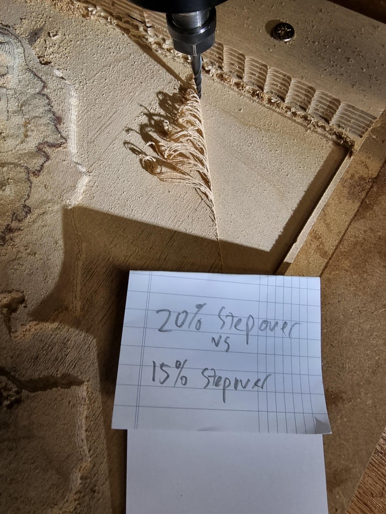
Select the model border vector and select the 3D Finishing Toolpath icon, and again choose Selected Vector. I find that a 1.5 mm diameter ball-nose taper (9-degree) upcut carbide bit works well. If you use a larger-tipped bit, the detail of the terrain is compromised. I use 10% stepover (so for a 1.5 mm diameter tip, that is 150 microns per cut line). Anything more than that and I can see raster lines, and sanding them off is a LOT of work, especially if the terrain is mountainous. Either Offset or Raster works fine, but think about this carefully if you can see the raster lines, as it will very much affect the look of the finished piece. Offset circles around from the center outwards, producing an interesting pattern of concentric polygons. If you like the look of straight raster lines instead, you should also carefully decide what angle they are cut at. A Raster Angle of 0 is horizontal, with a positive angle (less than 90 degrees) sloping from upper right to lower left. If you do select Offset, choose Climb. Unfortunately, Raster alternates between climb and conventional cuts, so may produce a more prominent rastering texture. It seems to cut most of the wood on the conventional direction cut, due to the bit pulling itself laterally into the wood.
Since the finishing bit is removing relatively little wood in fine chips or dust, you can go as fast as your machine can go.
Here is a video of my MPCNC doing finishing with the Offset strategy. I am limited by the Z motor’s speed. I usually set the feed rate to 50 mm/sec which for a 3D g-code command gets applied also to the Z axis (plunge rate is irrelevant for this toolpath, especially thanks to the cutout we did.). When I pushed the feedrate too fast (my X and Y can go much faster than 50mm/sec) I lost steps in Z and cut a big groove into my workpiece and ruined the job (see photo). Thus, it is a good idea to do some air-cuts with the bit zeroed way above the workpiece, going over the steepest parts of the model, and then carefully measure whether any steps were lost in Z by checking the bit height at the end compared to what you set it with at the beginning. Your machine may tell you if it loses steps, so check that. Again, it pays to do some practice runs on scrap wood to dial in the desired feed rate that works for you and your machine.
Step 5: Carve the Wood!


Step zero of CNC carving is having a level spoilboard (meaning, parallel to the machine’s X and Y axes, not necessarily perpendicular to the Earth’s gravity). If you have not already done this, go through the process of cutting a nice new flat surface across your spoilboard with a surfacing bit. Be sure to wear a dust mask. If the surface looks or feels scalloped, adjust the tramming (perpendicularity) of your spindle until it is perpendicular to the surface, and face the spoilboard again. It is not a bad idea to move the spindle around your spoilboard with a bit or dial gauge installed and measure how level and smooth it is at several locations like a 3D printer does before it starts a print.
To attach the stock, I use both tape and screws. First vacuum any dust off the spoilboard. I use a combination of strapping tape on the underside of the workpiece, with strong thin double-stick tape between that and the spoilboard. Use just a few pieces here and there, no need to overlap strapping tape (see photo). If the depth of your cutout pass was too much, you will be glad you did this. I even stand on it for a minute to make sure the double-stick tape is well stuck. I use TESA 4298 blue strapping tape that leaves no residue, yet is very sticky. The CA-glue-and-two-layers-of-masking-tape approach may be fine also, but watch out for it being too thick or uneven due to tape overlap.
In addition to the tape, I usually drill through-holes in the corners of the stock outside the model region and use long wood screws to fasten it firmly to the spoilboard. You should not be able to poke a thin piece of paper anywhere under the workpiece. You may prefer to use clamps. I find they can come loose or the bit may try to do a rapid through them and break, especially in a classroom setting with less experienced users. Once your material is well fastened, it is time to Home the machine as per the manufacturer’s instructions (set machine coordinates' origin) and zero the bit to the lower left corner of the material (or wherever you had set the working coordinates' origin when you started designing in VcarvePro). It helps to do this with a pointy bit like your finishing bit or a V bit. Mark the wood at that point in case you lose power and have to re-zero to the exact same place later. (Yes, that has happened to me.) Then set the Z zero of the first bit (cutout endmill) to the work surface. If you will be carving away the entire top surface during the roughing pass, be sure to make a block of wood for zeroing to this exact height again later. I use two identical smooth hardwood wedges (from a toddler toy blocks set) slid against each other and taped together, as a variable height Z-zeroing block. Now is your last chance to ensure your wood has not become warped or your CNC misaligned, and check whether the bit touches the surface at the zero Z height all over. If it is within one mm or less all over, you should be OK. If it is not, you risk having a flat-top peak or cutting through the workpiece.
The cutout and roughing toolpaths produce a LOT of wood chips! Wear eye protection, ear protection, and a dust mask. Be ready with the shop vac or have a vacuum attachment (or blower) to keep them from causing problems by getting in the way of the cutter. This also reduces the fire hazard in case a hot bit were to break and land in shavings. Supervise this pass closely always!
In my experience, the finishing toolpath may take over 8 hours of continuous carving, which can be grueling with continuous supervision. It is best not to wear ear protection for this pass (unless you have a loud router) because your ears will tell you if something has gone awry first. Certainly wear a dust mask, for all of the carving. I use a positive pressure ventilator face shield, which is more comfortable to wear all day and accommodates my glasses without fogging up. Many woodturners use these. Not cheap but worth the money.
Step 6: Post-processing and Sanding the Carving


When the finishing toolpath is finished, unfasten the work by removing the screws and carefully prying up to unstick the tape with a chisel or similar tool, being careful not to gouge the work. Cut off the excess wood with a bandsaw, coping saw, jigsaw, or scroll saw. Leave a mm or two of the thin bit at the bottom of the cutout pocket when you are cutting, to avoid marring the edges with your saw. Sand that lip off with a belt sander, along with any marks left behind by the cutout bit. If it is a curved shape, you can use an oscillating drum sander or just a lot of hand sanding. You could also use a router table, if you have one, to cut off the lip with a roundover bit.
All but the hardest woods will have some fuzzy fibers remaining on the terrain surface after the finishing pass, even with a 10% stepover. I have spent hours and hours sanding these off by hand with a small piece of 200 grit sandpaper, but a quicker and, for some rough terrain, more effective approach is to buff them off with abrasive sponge wheel attachments (something like this) for a Dremel or similar motorized hand tool . That allows you to get down into the valleys and details without changing the shape of the terrain. If you have a choice, choose wood-colored buffing abrasive sponge wheels as some grit may become lodged in the cracks. Use a low Dremel speed so as not to melt glue. Try buffing in a variety of directions to see which removes fibers the best, depending on which way the grain is going in the layer you are working on. Wear a dust mask and eye protection while buffing/sanding!
Use sandpaper folded in hand, and/or on a sanding block, to get rid of any imperfections on the edges, corners and back. On the back, you can use a power vibration sander, with the piece resting on a block of foam rubber. And for flat edges, you can use a belt sander. Use progressively higher grit numbers from 120 up to 400 until everything is smooth and defect-free. Blow off the grit and dust with an air compressor if you have one, or a can of spray-duster.
Step 7: Finish the Carving


Finishing wood is always a contentious and personal topic, so if you don’t like the gloss effects of my work, do what works for you. I like clear spray varnish that does not yellow the wood much and I have found that gloss varnish brings out the chatoyancy of the wood (the optical effect that it turns light and dark depending on the angle the light is coming from.) Since plywood plies are oriented with alternating grain, you get really nice highlighting of the terrain levels that way.
Use a good quality spray varnish/lacquer (polyurethane or acrylic). Using a brush or rag is fraught with problems. Just say no. Do what furniture and car manufacturers do and spray. You may find the cheap spray varnish is all propellant and one can barely does one or two coats. Wear an organics-absorbing mask while spraying. Spray each coat lightly, with a bright light reflecting so you can see when the surface is just wet. You don’t want drips filling up your riverbeds. Let it dry completely between coats so that you can do a bit of hand sanding with folded 200-320 grit sandpaper in between coats. Expect this to span several days. You can also use the Dremel buffer wheels, but don’t melt the varnish – use low RPM and a tapping movement. Sanding between coats will smooth out any remaining wood fibers sticking out, and help the next layer to stick. Use your fingers more than your eyes to decide what needs sanding. Don’t sand after the final coat. I use at least 3 coats, sometimes up to 7, to get a finish I am happy with. It is a good idea to finish the back and edges, even if they will not be seen, to reduce water absorption and warping due to changes in the weather. If you have a sprayer that you can fill with any sort of varnish, then I recommend water-based finish, like Minwax Polycrylic or Smith and Rodger Rocktop.
Step 8: Add Final Touches


There are many possible enhancements you can do with your terrain carving at this point. I poured an epoxy resin ocean on some of mine. That is a topic already better covered elsewhere since it is very tricky and involved. I will include a few photos...
Others have combined CNC carving with laser engraving to put roads or other customizations onto their terrain. This is another advanced topic and requires a laser engraver with a motorized Z axis.
You may wish to make or buy a frame for your carving. For mine, I build a sub-frame out of plywood offcuts that I can use to set the depth of the terrain behind the overlying frame. This subframe has wood screws at the joints so it can be loosened, adjusted and tightened and finally made permanent with a bit of foaming Gorilla polyurethane glue.
One option that I always do is to print a map to hide behind the carving. When people want to know what the location of some feature is, they can look at the printed map and find it. Here is where it comes in handy to use the screen captures of the model area you made when you were playing with the parameters in TouchTerrain. You can also use Google Maps with the Terrain layer switched on so it will resemble your carving. I print them on the best paper and at the highest resolution my printer can handle, and then laminate them with a laminator. I tape them to the back of the model with a Kapton tape hinge, so they can be swung out from behind the model easily (see photos). You may wish to customize the map printout, or the carving itself, with markers showing names, dates, or places of interest and special sentimental value.
If you are planning to sell your artwork, you may wish to create a brand to burn your name or logo on the back, as I did (see photos).
Choose a hanging method that will not fail due to the weight of the artwork and its frame. It will be heavier than your average painting! Because there is a strong desire to touch the model and feel its texture, be sure it is well hung and the hook well mounted to the wall. Anchor hooks into a stud inside the wall, ideally.
Step 9: Photographing and Sharing Your Work

Share your terrain carving artwork here or if you have photos elsewhere, please link them here in the comments! Take photos in sunshine ideally, or at least use a point-source spotlight. Experiment with different viewing angles and light angles. Like a real landscape, carved terrain’s personality changes a lot with the lighting, and shadows can add drama.
Also, if you have suggestions for improving this Instructable, please mention them in the comments. I am always learning!
Step 10: Appendices

Appendix 1: Stuff I Did That I Do NOT Recommend
- Using cheap plywood (except for practicing). Lots of knots and holes. Peaks may break off. Overlaps in the layers.
- Too big of a (3 mm+) ball nose for the finishing passes. Scalloped surface. Use a finer one.
- Using the Fusion 360 "add-on" for creating the model. This add-on is limited in the allowed size of model and is very slow, buggy, and difficult to use.
- Tiling lots of USGS data together. Tedious to align all the tiles properly.
- Working with grayscale GeoTiffs. Lots of pre-processing and model creation is needed that Touchterrain does for you.
- Attaching the workpiece with not enough double-stick tape (or poor tape). It came detached while carving.
Appendix 2: Other’s Tutorials
The most impressive work I have seen is by Dom Riccobene, who has many, beautifully filmed time-lapses of carving terrain on YouTube and Instagram (@DomRiccobene). He is a true artist, coming up with clever approaches to create works of art with a CNC that often involve terrain carvings. He has a paid tutorial on Patreon. ($5.50/month). “Digital Sculpture: A Beginner’s Guide”. He uses SRTM30 data from OpenTopography, Blender, Aspire. He designs artsy concrete pavers in his day job.
Dom Riccobene
https://www.youtube.com/c/DomRiccobene/videos
https://www.dom.riccobene.com/
https://www.patreon.com/DomRiccobene
Instructables:
2020 By Garage_Shop_Crafter in Workshop/CNChttps://www.instructables.com/Making-Custom-Wood-Carvings-From-Topo-Maps/
2016 By shapespeare in Workshop3D Printinghttps://www.instructables.com/Make-3d-Printed-Topo-Maps-of-Anywhere/
2016 By KurtisS3 in Workshop/CNChttps://www.instructables.com/3D-Topo-Map-Generation-to-CNC-x-carve-Shapeoko-2/
2014 By pgarrow in Workshop/Tools
https://www.instructables.com/Machine-Carved-Contour-Map-I-Made-It-at-TechShop/
YouTube:
2014 3D prints by Shapespeare https://youtu.be/bzwybr65I9o
2018 Winston Moy
Carving a Topographic Map of Colorado from an STL - #131 [CNC]
And another one he did for Carbide 3D’s channel: https://youtu.be/8eqRxFwYDmg
2018 Vectric - Edward Powell
Tips & Tricks | Creating a 3D Terrain Map
2020 BG Precision
3D Terrain Carving CNC Step-by-Step Guide (using Fusion 360 and Blender)
2021 Proun Goods
MPCNC 3D Mountain Carving - Denali
2021 Jonathan Katz-Moses
3D Wood Topographical Map made from Dyed Skateboard Veneers
Appendix 3: VcarvePro Vs. Fusion360
These are the two CAD/CAM packages I am most familiar with. There are plenty of others you may wish to consider as well.
Fusion360
Fusion360 is a huge full-featured CAM package by Autodesk (who runs Instructables). The full version is quite expensive ($545 per year subscription). Thankfully, it is free for hobbyists, small startups, and educators, with some limitations. It was created for designers of complex, usually metal, devices and products. It was NOT designed with woodworkers and artists in mind, who usually do not need its amazing levels of accuracy and 3D design, including mechanical simulations of component interactions. Features of use to woodworkers have been added reluctantly and slowly, only after they reach some threshold of votes from users on the Autodesk forum. I know: some of my suggested improvements are still in their To-do list after 5 years. F360 still does not have an option to add a V-bit to your tool library. You have to pretend it is a “chamfer mill”. If you already know CAD (computer-aided design) or love the idea of learning it, you will not be disappointed by the power of F360.
That said, I can’t count how many hours I have wasted trying to do one simple thing in F360 that should have been easy, such as selecting a large number of features in a model, or resizing a model, or just cutting and pasting a feature. The software has a philosophy that is very much geared toward parametric models. These allow you to change features by changing one parameter, and the other parameters that depend on that one will change automatically. This is great for manufacturing widgets, not so much for making art. I find that it often prevents me from adjusting features because they are locked.
The CAM (computer-aided machining) side of F360, now called Manufacture, is quite powerful and has toolpath strategies of use for woodworkers not found in other packages. So one option to avoid many of the hassles of F360 is to design your work in another package and import it into F360 only for its CAM.
If you need support for how to use Fusion360 or to report a bug, you are referred to their forum, which may or may not be of help. Personalized support is non-existent. There are many YouTube videos that will help you learn it.
A free and open alternative to F360 that may be a bit more user-friendly and is nearly as powerful is FreeCAD. I have not used it enough to offer an informed opinion of it yet.
VcarvePro
This software by Vectric Ltd. is designed by and for woodworkers. It is not cheap ($700 in 2022 – to own, not a subscription like F360), though there is a Makerspace Edition that is quite reasonable if you are part of a makerspace. I paid for my VcarvePro as a bundle with my Handibot CNC machine. To carve terrain models, you could probably use VcarveDesktop, which is only $350 (in 2022), but I have not used it. Unlike F360, I always find VcarvePro a pleasure to use and consider it well worth the money. Vectric’s personalized customer service is fantastic - email replies in one day or less! Bugs are fixed quickly. The video tutorials produced by Vectric are excellent. There are also some great YouTubers out there with Vectric tutorials, such as Mark Lindsay.
For the true artists out there, I recommend Vectric’s top-of-the-line Aspire, which is VcarvePro plus lots more tools for creating your own 3D models freehand for woodworking. It is not at all like a CAD package for making widgets, but one with the flexibility and personality to mold 3D shapes in an intuitive way, and powerfully combine them with text and other features of interest to woodworkers.
CAD/CAM Conclusion
I once spent a day creating a complicated test design to calibrate and benchmark my MPCNC machine after I finished building it. I chose to use Fusion360, which I have used to design many other complex objects, so I am well familiar with using it. It took me all day, and my toolpaths caused the machine to halt at random, for unexplained reasons. The next day, I tried again using VcarvePro. Starting from scratch, I got the same design drawn up and exported into toolpaths in about an hour. They worked the first time, with no halting or other problems. If you want ease of use, I can’t recommend Vectric software highly enough. I absolutely love it. If you want the most powerful free-ish CAD/CAM software and are willing to learn its vagaries, go for Fusion360.
Second Prize in the
CNC and 3D Printing Contest


