

Introduction: Cheap Scalable Arduino CNC, Plotter, Mill, 3D Printer... (MPCNC)
This project is based on Allted's design CC BY-NC 3.0 It is a popular design known as MPCNC, or "Mostly Printed CNC." Allted hosts a full website (Vicious1) with loads of additional information and details.
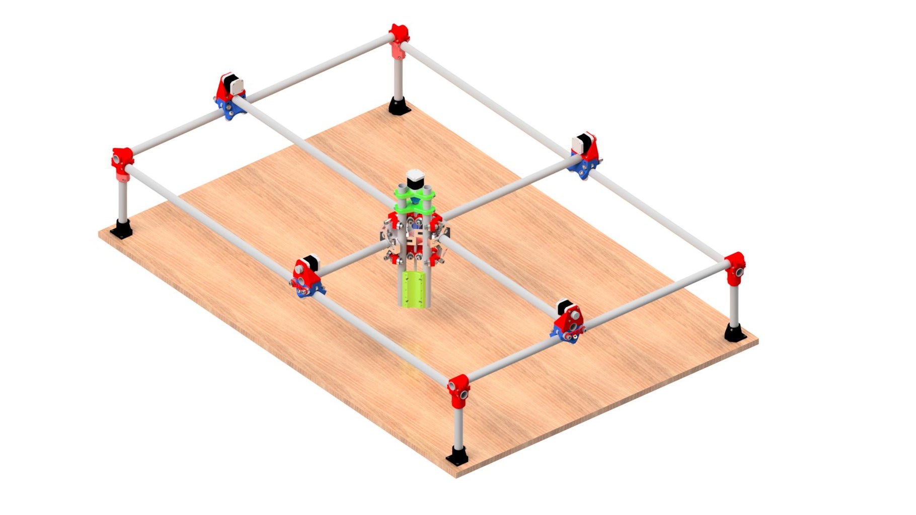
In this Instructable I'll show you how to make a cheap scalable CNC machine controlled by Arduino. My printer has a usable volume of 1500x1000x200mm. It will provide a computer controlled plate where you can add any kind of tool for your application: laser, mill, drilling machine, 3D printer head, pencil…
In order to maximize customization capabilities and reduce costs:
- Most parts are 3D printed
- Open source hardware / software
- Tube profiles work as Rails
If you are looking for a CNC but don’t want a single purpose thousand-dollar machine, this is your project!!
Be sure to watch the video above, and if you like it please consider subscribing to my channel which has been recently created and will be updated with new amazing projects.
Before starting you should know the usable length, width and height you want for your machine. The less heigth (Z) the better.
Step 1: Tools I Used
In order to follow this instructable, it is supposed that you have access to a 3d printer or 3d printing service.
You will use:
- 3d Printer (or 3d printing services/friends)
- Screwdriver
- Allen wrench key set
- Pliers
- Cutting pliers or scissors
Material required:
- 1.8Kg filament (ABS is more durable, PLA is easier to print)
- 1 x Ramps 1.4
- 1 x Arduino Mega 2560
- 4 x GT2 16T
- 53x 608 Bearings (2-RS, Z, ZZ)
- 5 x Nema 17 Stepper (Recommended ≥2A)
- 3 x Stepper Drivers A4988
- 12V 3A power source
Bunch of Zip Ties
3d printed parts:
- Link to stl of parts (Thingiverse) (Allted's design) or shop
X, Y and Z dimension dependable materials:
- 25mm OD steel tube:
- 3 x Rails X = Usable Width + 264mm
- 3 x Rails Y = Usable Depth + 264mm
- 2 x Z Rails = Usable Height + 190mm
- 4 x Legs = Usable Height – 13mm
1 x Allthread = Usable Height + 76mm
- GT2 belt (2 x Usable Width + 2x Usable Depth)
- Wiring to extend stepper Wires (at least Usable Width + Usable Depth + Usable Height)
1x Allthread = Usable Height + 76mm
Bolts-nuts:
- 1 x M8 Threaded Rod
- 1 x M8 X 130
- 12x M8 X 65
- 2 x M8 X 40
- 28x M8 X 30
- 43x M8 Nylock Nuts
- 1 x M8x 25 Coupling nut
- 19x M3 X 10
- 57x M4 X 20
- 57x M4 Nylock nuts
Step 2: Legs


To make one leg:
- First, take the “Botom corner” part, and fix it to “Lock_Corner” part with a M4x20mmbolt and nut. Beware of the joint shapeto match them.
- Take one of the leg tubes (Usable Height – 13mm long).
- Insert one edge of the tube in the “IE_Foot_Bottom” hole and fix it with another M4x20mmbolt and nut tightly.
- Insert the other edge of the tube in the “Lock_Corner” hole and fix it (M4x20mm + nut) keeping the bolt loose.
WELL DONE!! You have made one leg! Repeat this process with a second leg. Then you have to make two more legs using “BotomM_Corner” and “LockM_corner” which are symmetrical to the non-M parts. Then you have four legs to support the machine.
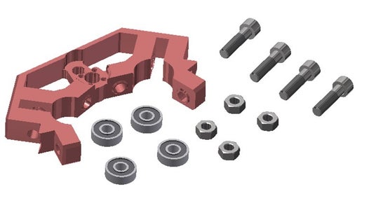
Step 3: Carriage


Take the “Roller” part
- Use three M8x30mm bolts to fix three 608 bearings. It will be easier to adjust at the end of the projects if nuts are facing to each other as in the photograph.
- Don’t tight too much, just to fix the bearing in position.
Adding the “RollerPlate”:
- Then take the “RollerPlate” part, four bearings and two M8x60 bolts.
- Insert two bolts on the “RollerPlate” leaving the span rings of the “RollerPlate” in the opposite side of the bolt head.
- Insert one bearings in each bolt.
- You must insert the bolts with the “RollerPlate”-bearing sandwich in the two remaining holes of the “Roller”. Pay attention to the direction of the “Roller”, the flat face with two rings should face the bearings. While inserting the bolt put another bearing in each bolt.
- Add a lock nut to the edge of each bolt.
Repeat this process to have two “Roller” and two “RollerM” completed.
Insert the rollers on their rails (one "Roller" and "RollerM" for X xis and another pair for Y axis). You should insert them with pressure and then, the four rollers should slide easily and equally.
Step 4: Structure


Prepare the structure:
- Put the legs assembled in step 1 in an approximate location.
- Over the legs add the Y axis tube (rail) with the roller mounted. The "RollerPlate" must be facing outwards the machine, don't forget it!
Secure it:
- Add a "Spacer_Corner" over each leg on top of Y axis tube and put the X tube over it.
- That spacer will secure the X axis tube. Place the "Top_Corner" and secure it with four M3x20mm bolt and nuts. Don't tighten them because calibration will be required further.
Verification:
- Measure the distances between legs (or "Bottom_Corner" parts) to assure that in both X axes the legs are equally distanced. Repeat it for Y axis.
Step 5: Z Axis


Nut traps:
- Take the two "Nut Trap" parts and four M4 nuts
- Insert the nuts into the holes. Put the locking face (the one with rubber) outwards.
Tubes:
- Take the two tubes for the y axis (Usable Height + 190mm).
- Make two holes on each tube coinciding with the "Nut_Trap" holes (at 22,5mm and 75mm from the bottom).
Assembly
- Insert one “Nut_Trap” in each tube until holes coincide.
- Take the “ToolMount” and fix it to the tubes with four M4x20mm bolts.
Z-lower:
- Take the "Z-Lower" part. Insert it in the tubes.
- Put the bearing housing facing opposite to the tool mount side. Pay attention on how it is mounted, the edge if facing to the back of the tool mount.
- Insert a 608 bearing in the housing.
Z-Motor:
- Take the "Z-Motor" part and a Nema17 stepper. Attatch it with three M3x10mm bolts
- Take the "Pineapple_coupler" and attatch it to the motor shaft with two M4x20 bolts and nuts.
Full Z assembly:
- Insert the mounted Z-motor on the tubes, leaving some mm to the pineapple couplet to freely turn.
- Then insert the threaded rod in the bearing and fix it to the "Pineapple_Coupler".
- Fix the "Z-Lower" and "Z-Motor" With four M4x20mm bolts.
Step 6: Middle Pre-assembly


XYZ pre-assembly:
- Take the "XYZ" part, 4 bearings and 4 M8x30mm bolts and lock nuts.
- Insert the bolts-bearing stack as shown in image. Look how bolts are inserted.
- This bolt will not be touched. Assure bolts are tightened and that bearing turn freely.
- Repeat it for the other XYZ part.
XY pre-assembly:
- Take the "XY" part, 4 bearings and 4 M8x30mm bolts and lock nuts.
- Insert the bolts-bearing stack in the housings, as shown in image.
- This bolt will not be touched. Assure bolts are tightened and that bearing turn freely.
- Insert one more bolt-bearing.
Nut-Lock pre-assembly:
- Take the "Nut_Lock" part, Coupling nut and one M4x20mm bolt and lock nut.
- Insert the Coupling nut in the housings, as shown in image
- Align Coupling and lock nut faces.
- Then Lock it with the bolt-nut.
- This bolt will not be touched. Assure bolt is tightened.
Step 7: Middle Assembly


Take the "XYZ", "XY", one bearing, coupling nut preassembly and a M8x130mm threaded rod:
- Insert the rod in the centre of the "XYZ" on the hole which is lowered to house the Bolthead / nut
- Insert then the C"Nut-Lock" hole (NOT the coupling)
- Then insert the "XY" part with a bearing inside. Beware of the "XY" part position in the insertion. Look for the downwards protusion to orient the "XY" part.
Second part:
- On the previous assembly, insert the other "XY" part with another bearing analogously inserted.
- After that insert, the "Spacer" in the rod (with the small protrusion of it towards the "XY" part).
- The last part to add in the stack is a "XYZ". Then lock the rod.
Stack hardening:
- Take four bearings and four M8x60mm and nuts.
- Insert the bolt in the aligned holes of "XYZ" and "XY" adding a bearing in the inner edge of the bolt.
CONGRATULATIONS! your stack is ended.
You're almost done.
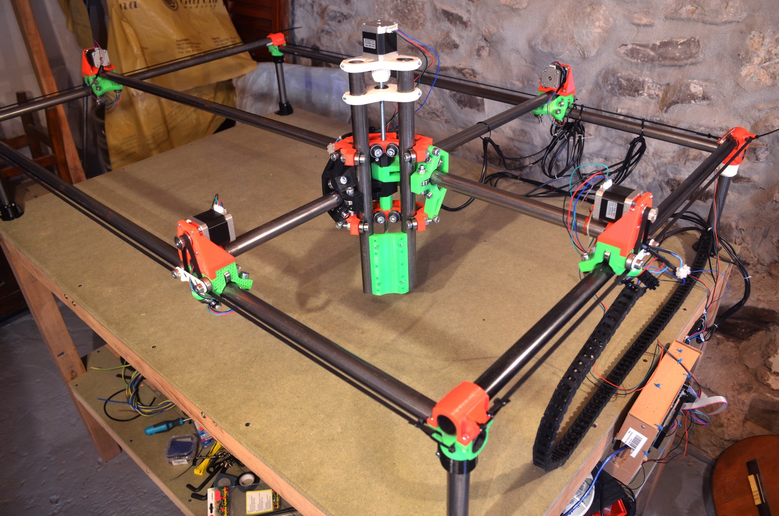
Step 8: Full Gantry Assembly


The hardest is done.
- Take the middle assembly and insert one tube on each "XY" part. In the X axis direction, you will insert a X rail (Usable Width + 264mm), while in the Y axis a Y rail. The rail must enter with pressure towards bearings and then move "freely" (or quite easily).
- Now, take the Z axis and insert it in the middle assembly. The stepper motor must be un the upper part.
- Take the full middle assembly and mount its X and y tubes over the rollers. Try to align the tubes with the roller face.
Now you have something similar to a machine. Let's add some motors to it:
- Take a "Roler_Mount". Add a stepper to it with four M3x10mm bolts.
- Put a GT2 pulley on the motor axis.
- Mount the "Roller_Mount" over one Roller and fix it with two M4x20mm bolts.
- The pulley must be facing outwards the machine.
- Repeat this until each roller has its motor mounted.
Step 9: Hardware Comes In...


There are two steppers per horizontal axis. They can be wired in parallel or in series. If wired in parallel, to have 2A in each motor it will be neede a 4A driver (which I don't have) But If wired in series a 2A driver can supply 2A to each motor. Because of this serial connection is desired for our project.
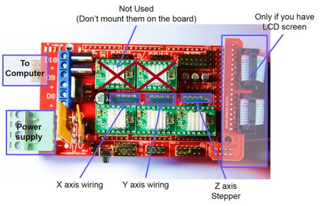
Wiring:
- You will need two sets of wire for series connection.
- Follow the scheme in the first picture for appropriate wiring.
- Mount the RAMPS, board over your arduino MEGA 2560.
- Then, connect the steppers to the RAMPS 1.4 board where shown in the second picture. To avoid damaging other drivers remove (if come mounted) the top two drivers which won't be using for now. You may need them for 3D printer capabilities.
- In the RAMPS power source connect the 12V power source. Match the "+" sign with the positive of the source.
Belts:
- The belts go from one corner to the opposite one.
- Use Zip ties to tighten the belt. First bend the belt over it and tighten a zip to make tooth contact.
- With a second zip, pass it through the corner hole and then the belt hole to finally close the zip.
- Then, the belt is guided through the roller bearings up, trough the motor pulley, then down to the other roller bearing and directly to the opposite corner.
- In the second corner fix it with two zips.
Hardware connection was quite easy after all.
Step 10: Software (easyer Than It Seems)

You now have a PC and an Arduino so you will need software bor both. First lets see what we need:
PC:
- Arduino IDE: It will upload required firmware to your arduino.
- CNC controller: It will control the machine sending command to your arduino.
- CNC generator: A software to generate the file with the machine movements.
Arduino:
- Marlin firmware: This software can receive commands (from a pc, a sd card or by lcd) and translate it into machine movements.
Upload Marlin firmware to your board:
- Download the arduino IDE (Arduino 1.X.X). The current version will not work when compiling, so please download the mentioned one.
- Download the Marlin firmware (Click here).
- Open the marlin firmware with the arduino IDE.
- Connect the arduino MEGA to the PC via USB
- selecting Arduino Mega in Tools→Boards→Arduino MEGA 2560)
- Choose the serial port for your Arduino board: Tools→Serial Port→ comX
- Upload the firmware to the arduino mega (Button pointing right in the upper part of arduino IDE)
As a CNC controller Repetier Host can be used.
CNC generator: It will depend on your final use of the machine. I will show some programs I have used depending on technology (although there are plenty more on the web):
- 3D printer: Slic3r + Repetier Host
- Laser engraver: Inkscape + Grbl controler
- Plotter: Inkscape + Repetier Host
(First CNC / path generator and second CNC controller)
Step 11: Calibrate Your New Machine


This step is critical to achieve a good accuracy with the machine.
There are different methods to calibrate this kind of machine but here we will take the most practical one.
Dimensions (repeat it with Y axis):
- Measure the 2 x distances between legs
- Measure x distance between rollers holding the x axis reinforcement bar.
- The three distances should be the same. If not loosen up required corner or roller mount to assure the measurement.
Ortogonality:
- Measure the diagonal distances between legs.
- Both diagonals must be same distance
- Following the pythagorean theorem, the diagonal must be equal the square root of (X^2 + Y ^2).
Repeat Dimension and orthogonality calibration until you are comfortable with results.
Software calibration (Repeat it for Y and Z axes):
- Mark the gantry or "Z axis" position.
- By software, move the gantry in X axis (for example 100mm)
- Check how much has moved in the axis you want to calibrate
- If it hasn’t moved what should, then go to the marlin firmware (open it in Arduino IDE)
- In “config.h” page look for that axis (in this case X) steps per mm constant. There will be a step/mm value.
- Take that value, multiply it by the distance you wanted to move and divide it by the real displacement distance. You will get a new value. Overwrite the previous constant with the new calculated one.
- The bigger distance you use for the calibration, the higher accuracy you will get. I recommend using big displacement. In my 1500x1000 machine y used 1400 and 900 respectively. Could have used more but that accuracy was fine for my applications.
Step 12: ENJOY IT!


Now you have your new marvellous machine, is time to use it for your next DIY.
I hope it will help in further projects and remember sharing it with new instructables!!
HAVE FUN!

Participated in the
First Time Author Contest

Participated in the
Plastics Contest


