

Introduction: Code a Traffic Light in Tinkercad Codeblocks & Circuits


While Tinkercad is well known for its 3D computer-aided-design (CAD) and modeling capabilities, many users are unaware of the powerful coding applications also built within the Tinkercad platform. Through this Instructable, I will showcase two of these applications using a block-coding method inspired by Tinkercad's 2020 Block Code Contest and many of the lessons I implement in my middle school classroom.
Tinkercad Codeblocks - Codeblocks are a relatively new feature at the time of writing this in late-2020. Codeblocks allows users to learn how to apply computer programming skills and methods in a unique way, creating a 3D model. Like the 3D design features that Tinkercad is well known for, Codeblocks allows users to add and manipulate basic geometric shapes to make just about anything imaginable. Unlike the typical CAD platform however, users can only add, move, or manipulate shapes by adding lines of code through a block-programming method.
Tinkercad Circuits - What was once part of the legacy 123D application suite, Tinkercad Circuits allows for users to create analog circuits in a simple-to-use simulation program. By dragging and dropping components connected by wires and breadboards, virtually any circuit can be assembled and simulated. In addition to basic analog circuit design, users can also drop in ATTiny, Arduino, or Micro:Bit controllers to program circuits using either block-based or script-based methods.
And because both of these applications are built into the Tinkercad platform, they are completely free, user friendly, and compatible on just about every device! Through this Instructable, we will create a 3D model of a traffic light using Codeblocks(Part 1 of the Instructable) and then create a circuit with LEDs programmed to function like a traffic light using Circuits (Part 2 of this Instructable).
Step 1: Part 1 Step 1 - How to Use Codeblocks

Part 1 of this Instructable is creating a 3D model of a traffic light using Tinkercad Codeblocks.
After signing into Tinkercad, click on Codeblocks in the left-side menu. Like the 3D modeling app, you will see any existing Codeblock projects you've created or a blue button to create a new one. Once you click to make a new project, you will be able to open a template based upon a previous project (if applicable), or tutorials designed by the Tinkercad team.
If you've ever used Scratch or another block-based programming application, Codeblocks will look familiar to you. The big difference is that instead of seeing some type of animation preview window, we see a 3D work plane that we can control with our code. There are six categories of codeblocks we can use to manipulate our shapes.
- Shapes - This category of blocks allows us to create and add geometric shapes to our design
- Modify - This category of blocks allows us to manipulate any shapes, or groups of shapes, we have in our design
- Control - This category of blocks allows us to loop or repeat tasks
- Math - This category of blocks allows us create variables or manipulate numbers and quantities in our design
- Data - This category of blocks allows us work with any variables that are created using Math blocks
- Mark Up - This category of blocks allows us to add comments or messages throughout our program
Step 2: Part 1 Step 2 - Starting Our Model
You can create a shape by simplly dragging and dropping a shape block into your programming window, then press the play button in the top right corner to preview your code. You must press the play button each time you wish to see your code run.
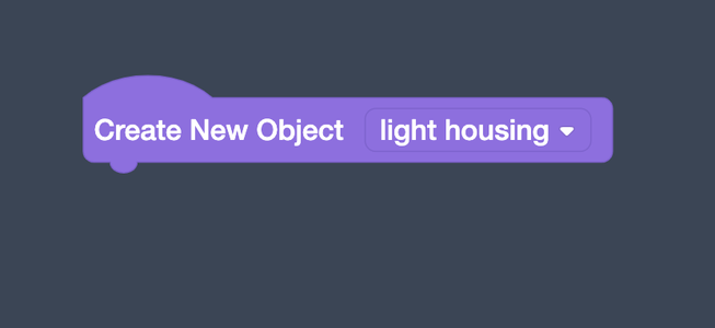
We are going to create an Object before adding any shapes. Objects allow us to manipulate or merge shapes together and consolidate our codeblocks. Our first object will consist of the main housing and light bulbs of our traffic lights. To start, grab a "Create New Object" block from the Modify blocks category and drag it into your programming window.
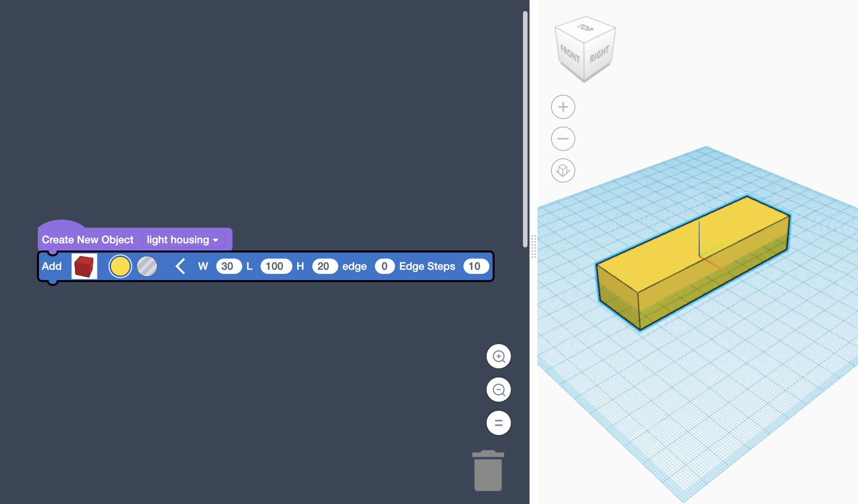
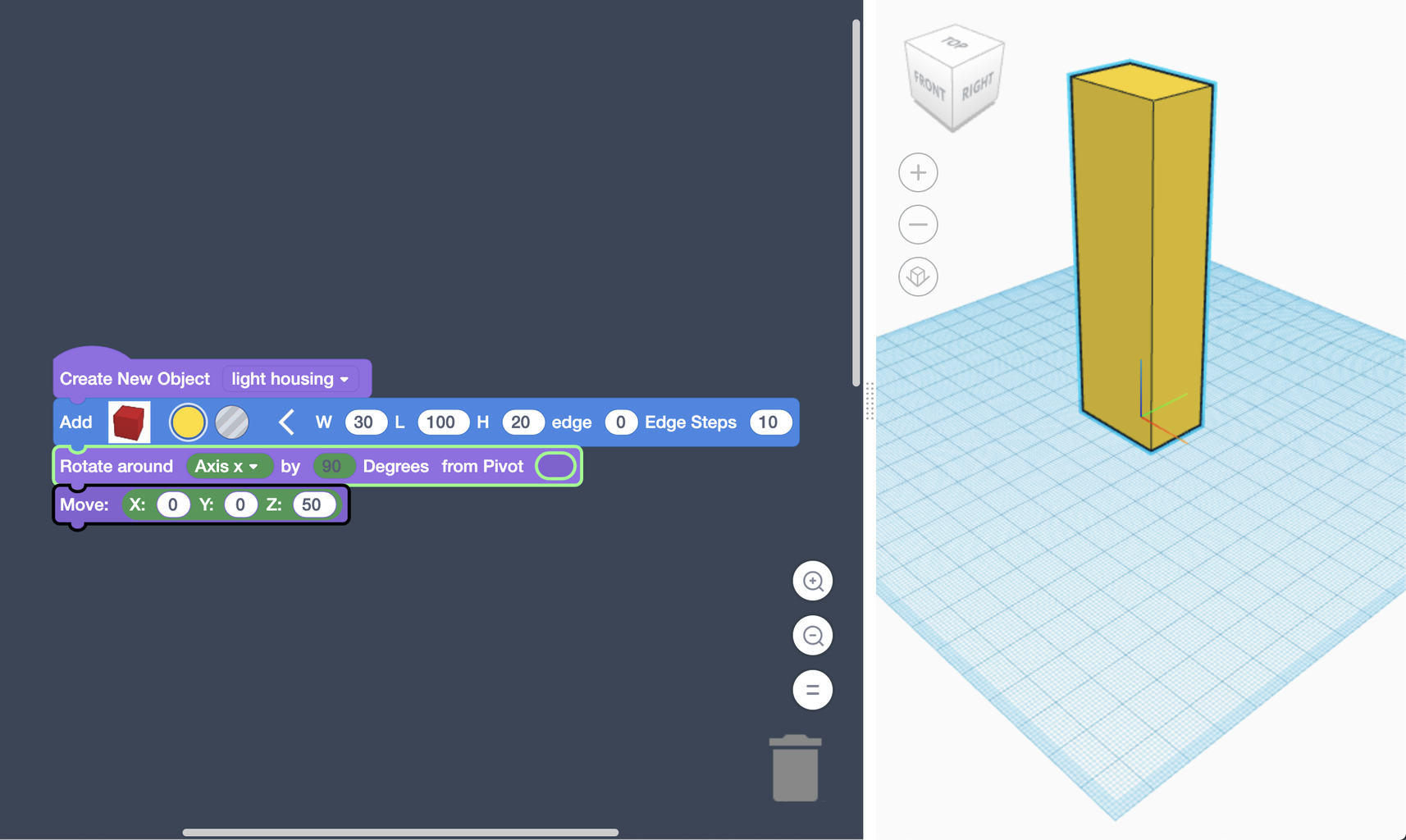
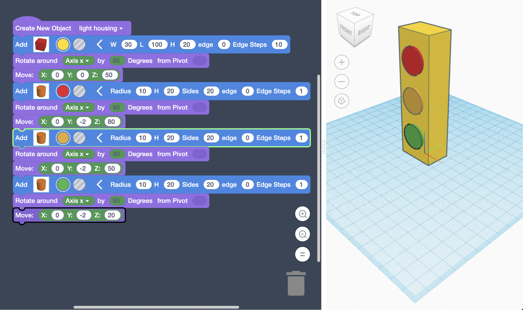
Next, we are going add a "Box" block from the Shapes category and snap it in place under our new Object. You can adjust the color and size of your box in the code block. Set it to be yellow, 30 W, 100 L, and 20 H. We will then rotate our box by adding a "Rotate" from the Modify category. By Rotating around the X-axis 90 degrees, we will stand the yellow box up vertically.
Lastly, we are going to add a "Move" block from the Modify category to life the box vertically so it is resting on top of the work plane. Drop your move block in under the rotate block and set Z to 50.
Step 3: Part 1 Step 3 - Adding Our Lights

Now that we have our yellow box to act as the main part of our traffic light housing, we will add cylinders to act as our light bulbs.
Add a "Cylinder" from the Shapes category snapped to our code from the previous step. Set this cylinder to be red with a Radius of 10, 20 H, 20 Sides, 0 Edge, 1 Edge Steps. We are then going to add a "Rotate" block and rotate our red cylinder around the X-axis by 90 degrees. Next, we are going to lift this cylinder using a "Move" block by setting Z to 80. Lastly, we are going to extrude the cylinder out of our box by setting Y to -2.
We should now have a red cylinder at the top of our light! We can copy the Shape, Rotate, and Move blocks from the red lgiht to create the yellow and green one with greater ease. Right click the red cylinder block and select duplicate. This will copy all three blocks we need, then snap them in place under all other code.
For the yellow light, change the color parameter on the cylinder block to be yellow, then set Z to be 50 in the yellow light's move block. We will again duplicate the three blocks of code from our red cylinder to make our green one.
After duplicating for the green light, change the color parameter on the cylinder block to be green, then set Z to be 20 in the green light's move block. You should now have all three lights!
Step 4: Part 1 Step 4 - Adding the Light Hoods


The last part of our Traffic Light model are the hoods that go above each light. We will be creating a new Object from our main housing as we will need to group shapes together and duplicate them to complete these parts, but we don't want these modifications to effect the shapes we already have (thus the need for a new object). Start by grabbing the "Create New Object" block from the Modifycategory and drag it in new space in your programming window.
We are going to add a yellow"Round Roof" from the Shapes category into our new object. We are then going to move this round roof above the red light cylinder using a "Move" block and by setting Z to be 90 and Y to -10. Next, we are going to add another "Round Roof" but set this second one to be transparent, or a hole, rather than a fill color. Add another move block to lift the roof hole by setting Z to 87 and Y to -10.
Lastly, we are going to add a "Group" block from the Modify category to the bottom of our hood object code blocks. This will group the yellow rounded roof to the hole rounded roof just like the group function in the 3D design portion of Tinkercad. We now should have our first light hood above the red light!
Next, we are going to create a new object so we can easily duplicate our light hood object two more times. Start by dragging another "Create New Object" block from the Modify category in new space of your programming window. Add a "Add Copy of Object" block from the Modify category, then drag the variable block for your first light hood from the Data category into the blank parameter of your modify block. This will add a new light hood overtop of the existing one.
We now are going to add a "Move" block from the Modify category and set Z to -30 to move the second hood over the yellow light. To complete our model, we are going to add another "Add Copy of Object" block from the Modify category to create another copy of our light hood. For this last hood, we are going to add a "Move" block from the Modify category and set Z to -60 to move the last hood over the green light.
And that concludes Part 1, Coding a 3D model of a Traffic Light using Tinkercad's Codeblocks!
Step 5: Part 2 Step 1 - How to Use Circuits
Part 2 of this Instructable is programming a simulated circuit using an Arduino to function like a traffic light in Tinkercad Circuits.
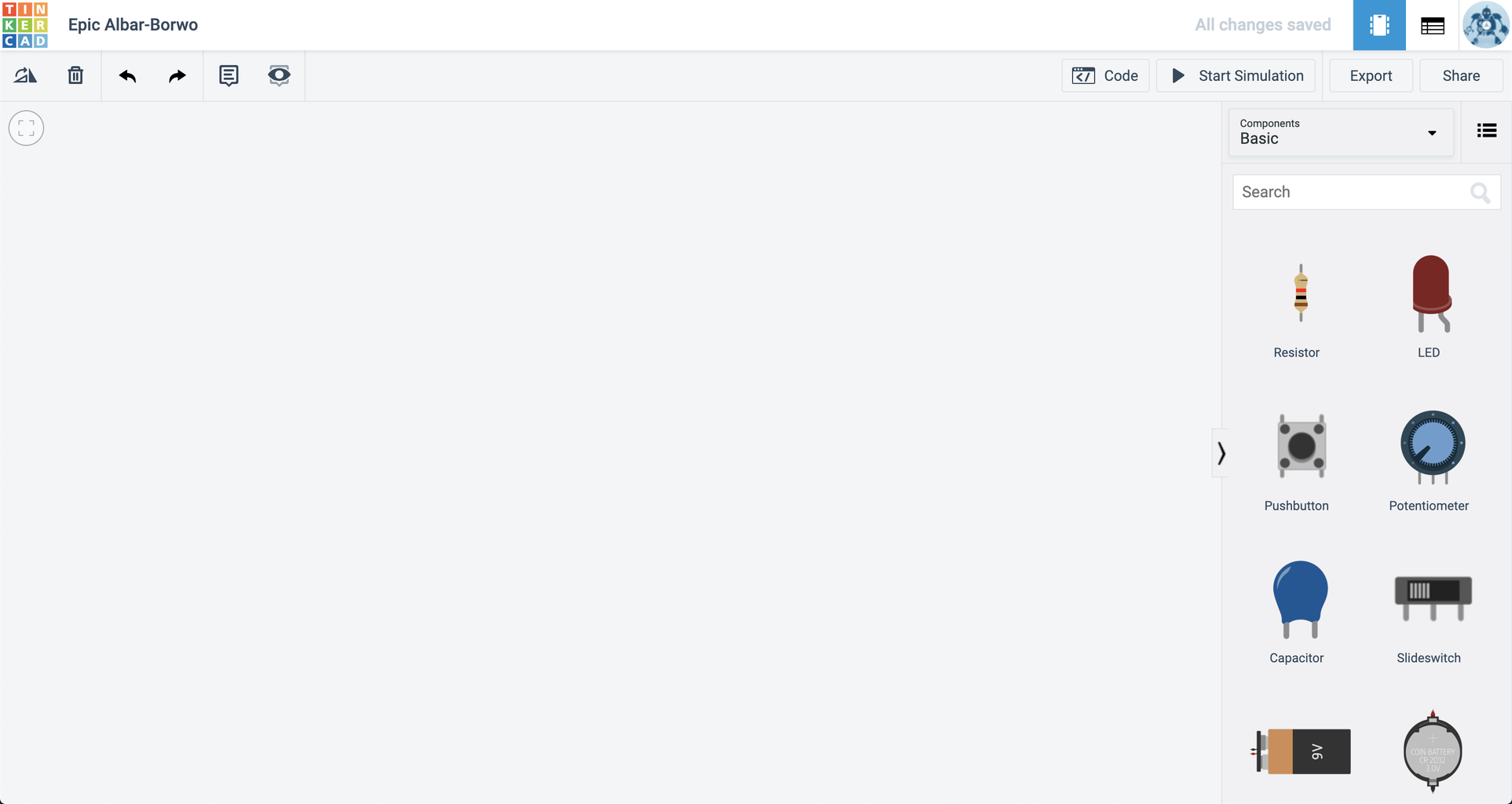
After signing into Tinkercad, click on Circuits in the left-side menu. Like the 3D modeling app, you will see any existing Circuits projects you've created and a blue button to create a new one. Once you click to make a new project, you will be brought to a blank document where you can drag and drop in components, or starter circuits made by the Tinkercad team.
Tools to rotate, navigate, undo, redo, delete, or annotate are in the top left corner of the toolbar. To add code, you can click the "Code" button in the top right corner of the tool bar, though no code can be added until a micro-controller component has been added first. To see your circuit in action, you need to press the "Start Simulation" button. Without the simulation turned on, no electricity is flowing through your circuit, its in a prototyping-mode. Once the simulator is started, you should see your circuit function as if it is truly connected using real components on your workbench in front of you.
To get started, you can drag and drop components from the component list out into your workspace. A simple click of your mouse will allow you to draw wires from component to component. Any options that are possible will be visible in an object menu when a component is selected (color, resistance, voltage, etc).
Step 6: Part 2 Step 2 - Starting Our Circuit

Before we dive into three LEDs (light emitting diodes), we are going to work our way in by adding a single light first. Start by dragging the following components out into your workspace:
- Arduino Uno R3
- Red LED
- 1K Ohm Resistor
- Breadboard Small
Next we need to connect your components together. Rotate the LED so it is facing right, then drop it into any two rows on your breadboard. Connect the resistor from the cathode of the LED to the black negative channel of your breadboard. This will provide a ground, or negative current, to your LED. LEDs can only handle so many amps (current flow of electrons before failing). A resistor allows us to control the flow of current to ensure we provide the correct amount of current our LEDs need. LEDs are also Polar, meaning they must be hooked up in a particular orientation for current to pass through. Resistors are Non-Polar and can be connected in any direction.
Next, connect a red wire from your LEDs anode to Pin 13 on your Arduino by clicking on the anode, moving your mouse (not click and dragging), and then clicking again on Pin 13. If you want to make bends in your wire, click your mouse as you move it across your workspace. Bend positions can be manipulated after drawing a wire.
Lastly, connect a black wire from a GND Pin on the Arduino to a pin in the black negative channel of your breadboard that the resistor is connected to. This will complete your starter circuit!
Step 7: Part 2 Step 3 - Starting Our Code

Next, we are going to program our red LED to blink on an off as we begin to put our code together! Start by clicking on the "Code" button to open your programming window. You are able to program your Arduino using both block-based and script-based methods, but we'll be focusing on blocks in this Instructable.
Like Codeblocks or other block-based languages, there are categories we can choose our blocks from to assemble our programs. Tinkercad Circuits has six categories:
- Output - This category of blocks allows us to send power to components out through our pins
- Input - This category of blocks allows us to read signals coming from components through our pins
- Control - This category of blocks allows us to manipulate our programs with delays, loops, or logic statements
- Math - This category of blocks allows us to utilize operators to enhance our logic functions
- Variables - This category of blocks allows us create variables as placeholders to increase complexity and function in our programs
- Notation - This category of blocks allows us to add comments or titles to our programs
To turn our LED on, we simply need to drag and drop a "Set Pin _ to HIGH" block from the Output category into our programming window. HIGH sends a high signal, or 5 volts, through whatever pin is selected in the block. Select Pin 13 as that is the pin we have connected our red LED to and 5V would turn the LED on.
Press Start Simulation and your red LED should turn on!
To make our red LED turn on and off, we need to first add a "Wait" block from the Control category and snap it in place below our set to HIGH block. For now, the time delay isn't important, but the duration set in your wait block will be how long the LED stays on, then off, then on again for.
Lastly, drag and drop another "Set Pin _ to HIGH" block from the Output category into our program. Again, select Pin 13 for the red LED, but this time select LOW. Low sends a low signal or theoretically no volts to our LED which would turn it off.
Press Start Simulation and your red LED should blink on and off repeatedly!
Step 8: Part 2 Step 4 - Adding LEDs

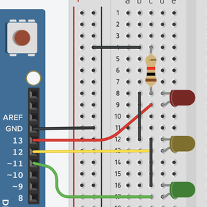
Now that we've completed a proof of concept with one LED, we can add our remaining two LEDs and complete our circuit! Drag in two more LEDs, set one to be yellow and one to be green. Match the order of a traffic light by placing the yellow light below the red one, then the green light at the bottom.
Like the red LED, we need to run part of our circuit through a resistor to prevent our LED from failing under too much current. You could add a resistor for each LED by matching the wiring method we used with our red LED in the second step. Alternatively, you could share the red LEDs resistor by connecting each cathode (ground) signal together. In a typical circuit, all components share a common ground. As a result, running ground through three resistors, one per LED, or one resistor shared among them would have the same effect.
Next, we will connect the anode of the yellow LED to Pin 12 and the anode of the green LED to Pin 11. Like before, the pin we choose is insignificant for this purpose, but I've chosen to use Pins 12 and 11 to keep our circuit organized.
Next, we need to program our LEDs to turn on and off by completing our code!
Step 9: Part 2 Step 5 - Completing Our Code
To complete our traffic light circuit, we need to add code blocks that control our yellow and green LEDs like we have for our red one. First, let's analyze the behavior of a traffic light.
- Red light is on, Yellow and Green are off, typically for a longerduration
- Green light is on, Yellow and Red are off, typically for a longerduration
- Yellow light is on, Red and Green are off, typically for a shorterduration
In the real-world, longer durations typically span two to five minutes while shorter durations last for ten to thirty seconds. In our prototype, we will use 3 seconds for our longer duration and 1 second for our shorter duration.
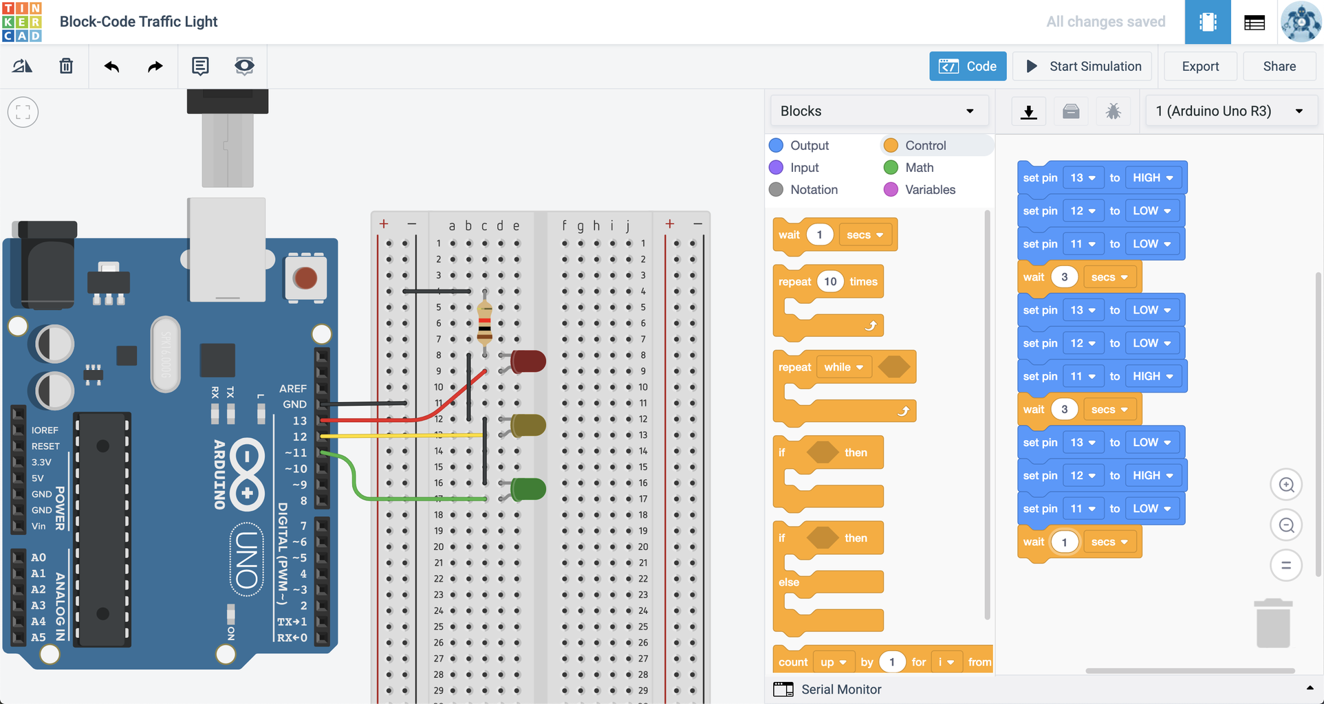
First, let's add two "Set Pin _ to HIGH" block from the Output category below our 13 HIGH block. Set one for Pin 12 LOW to turn off the yellow light, and the other to be Pin 11 LOW to turn off the green light. Next, set the Wait block to be 3 seconds to create a longer duration. This will have only our Red light on for a longer duration, as listed in step 1 of our traffic light behavior.
Next, let's duplicate all four code blocks we currently have by right clicking on our first block and selecting duplicate. Drag these four new blocks in place under our wait block. For this section, Pin 13 = LOW, Pin 12 = LOW, and Pin 11 = HIGH for 3 seconds. This will have only our Green light on for a longer duration, as listed in step 2 of our traffic light behavior.
Lastly, let's duplicate the four code blocks again by right clicking on our first block and selecting duplicate. Drag these four new blocks in place under our wait block. For this section, Pin 13 = LOW, Pin 12 = HIGH, and Pin 11 = LOW for 1 seconds. This will have only our Yellow light on for a shorter duration, as listed in step 3 of our traffic light behavior.
Press Start Simulation and your three LEDs should blink on and off like a real traffic light!
And that concludes Part 2, Coding a Traffic Light inspired circuit using Tinkercad Circuits!
Step 10: Code Files and Conclusion


Tinkercad's Codeblocks and Circuit features are incredibly powerful tools for anyone looking to develop skills in computer science! With user friendly interfaces, Codeblocks and Circuits makes learning how to create programs simple and fun.
See the sample project from Part 1 - Modeling a Traffic Light using Codeblocks here.
See the sample project from Part 2 - Creating a Traffic Light circuit and program in Circuitshere.
And if you're curious as to how the Traffic Light circuit would look like if you used a script-based language instead of a block-based one, check out this project. Moving into script-based programming languages are made easy in Tinkercad Circuits as you can utilize both simultaneously. For an added challenge, try to make your traffic light into a smart circuit by adding sensors that would detect a car to trigger when it should change from red to green!
Tinkercad is a powerful tool in all aspects of my classroom, whether it be for 3D modeling, circuit design, fundamentals of programming, or advanced programming. This traffic light project is one of my personal favorites and I hope you enjoy it too!
Thanks for reading, happy making!

Runner Up in the
Block Code Contest


