

Introduction: Commando Droid


3D printed Commando Droid With voice playback and illuminated eyes and chest.


Step 1: Overview
The Commando Droid .stl files were purchased from the following link:
This Instructable will provide information on the methodology I used to enhance the commando droid by using WS2812B LEDSs and adding audio. The focus of this Instructable is on the electrical components used and a brief summary of what was changed to incorporate the electronics. Paint and weathering information is also listed.
The project materials utilized are summarized below and a detailed list of the components for purchasing the materials is listed in Step 9 of this Instructable.
· (1) Arduino Nano
· (4) WS2812B LEDS
· (1) Panel Mount 2.1mm DC barrel jack
· (1) 12 VDC Wall Power Adapter (2000mA) – Connector 2.1mm plug
· (1) Step Down Regulator 12V to 5V
· (1) Electronics123.com, Inc. 4 Buttons Triggered MP3 Player Board
· (1) SparkFun Sound Detector
· (1) Speaker
· (1) Wireless RF Switch Long Range DC 12V 4CH Channel Wireless Remote
Step 2: 3D Printed Included File - Power Connection Box


I made a power box that mounts to the back of the foot as shown above. The box holds the 2.1 mm DC barrel jack used to connect a power transformer to the droid. The power box .stl file is included with this Instructable. Autodesk Fusion 360 was used to create the power connection box.
Step 3: Head Cap Modification


I modified the head cap to allow the remote-control box and audio card to be installed. The recess shown is to allow the remote-control box to sit flat. The modification can be easily accomplished by modifying the purchased droid files using 'Windows 3D Builder' that is included with Windows 10 or Autodesk Fusion 360.
Step 4: Head Modification

Autodesk Fusion 360 was used to modify the head as shown below. The modification required using Autodesk Fusion 360 to carve out areas on the existing head .stl file. I ended up making the speaker grill holes larger than shown below using a drill since they were too small once the head was printed.
Step 5: 3D Printed Included File - Speaker Grill


I created a small speaker grill that is installed on the bottom of the head as shown. The speaker grill .stl and Autodesk Fusion 360 file is included with this Instructable.
Step 6: Body Color


I used Rust-Oleum Gloss Purple paint for the droid. When I do weathering, I prefer to use a satin paint then black wash over it. Gloss paint does not provide a good weathering effect when black washing. The key to using gloss paint is to mute it down. To do this I sprayed over the gloss paint with Rust-Oleum Matte Clear spray paint. You must let the gloss dry for at least a few days and lightly mist over the gloss paint with the Matte Clear. If you spray the matte paint too soon or apply it too think, the gloss paint will crack and bubble. Once you have sprayed the gloss and then the matte paint, you are ready to black wash. I just put a blob of black acrylic paint on a disposable paper plate and then take a disposabel chip brush and dip it in water and load the brush up with the acrylic paint. Slop the paint all over the part and then use paper towel to wipe off the black acrylic paint to achieve the desired for effect. This provides a nice base to add rust and silver scrape marks to your project. I used 'Silver Rub and Buff' to create many of the weather effects. The key is to put the rub and buff on your droid as dry as possible and lightly rub. I found that dry brushing a little dark brown around the silver edges adds to the weathered look.
Step 7: Bronze Sections


For the shoulder joints, knee joints, mouth grill and areas on the outer arm sections, I used Art alchemy Bronze Age metallic wax I purchased on Amazon. This is simular to 'Rub and Brush'.
Step 8: 5 Arduino Nano Controller

The Arduino Nano shown above provides the control of the WS2812B LEDS and has an input that is controlled by the SparkFun sound detector. The Arduino is mounted in the head of the commando droid (Pin Side Up) so we can easily make the power and LED connections. The Arduino programming software is free and can be obtained from the following link:
https://www.arduino.cc/en/main/software
The wiring diagram provided as a pdf file in this instructable will provide you with all of the connections required.
The Arduino Nano was purchased on Amazon and controls the LEDS along with processing the Gate input from the SparkFun sound detector. When the SparkFun sound detector gate is active, The mouth LED will illuminate. When the SparkFun sound detector gate is inactive, The mouth LED is extinguished.
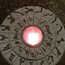
The Arduino Nano also controls the Chest light LED and fades the LED up and down. The eye LEDS are also controlled by the Arduino Nano and will blink the eyes at a random interval.
Step 9: Parts List


Step 10: Electrical Summary and Schematics


The wiring schematics are provided shown above are also provided as a .pdf file download in this instructable. A brief summary of the electrical circuit is listed in the following steps.
Step 11: Audio Playback

I used a (Electronics123.com, Inc. 4 Buttons Triggered MP3 Player Board with 10W Amplifier and Terminal Blocks) board that I purchased on Amazon to playback the audio files. The board uses a microSD card that you place your mp3 or wav files on. The electronics123.com website has very good instructions for using this module. The module has four (4) audio file triggers that will play an audio file when two terminals are shorted. The module can also receive a serial string to trigger several different audio tracks. For the purpose of the Commando droid, I am using the four (4) individual triggers. I will be using the serial interface for the Smelter droid since he will tell the time on the hour and requires the ability to playback several audio files.
Step 12: Audio Triggering – Remote Control

I used a (Wireless RF Switch Long Range DC 12V 4CH Channel Wireless Remote) that I purchased on Amazon to trigger the audio playback board. The remote switch has four relays and when a remote-control pushbutton is pressed, the corresponding relay on the board will activate. The four (4) relay contact are wired to the audio playback board. All of this is done without the Arduino involved. You can use most any remote switch since they are pretty much all the same.
Step 13: Audio Detection

I used a (SparkFun Sound Detector Audio sensing breakout) that I purchased on Amazon to detect audio level and provide a signal to the Arduino Nano when the decibel threshold is reached. I placed this board near the speaker inside the head. The board has a small microphone to detect audio. The gain for the audio detection can be changed and I reduced the gain around 70% using a resistor that can be soldered on the board. The instructions from SparkFun provides a table of gain settings and suggested resistor values. Their manual is quite good.
Step 14: Power

The remote-control box requires between (9 VDC and 24 VDC) to operate and the Audio Playback device requires between (8 VDC – 24 VDC) to operate. The Arduino and LEDS require 5 VDC to operate. To resolve this easily, I used a (BINZET DC Converter Step Down Regulator 5V Regulated Power Supplies Transformer Converter (5V 3A 15W)). This device converts the 12 VDC input to 5 VDC. By using this device, I have both of the required voltages available for use.
Step 15: Arduino Code
The arduino file is provided with this instructable and also listed below.
// Commando Droid Droid WS2812B and Voice
//John Guarnero 2020
#include <Adafruit_NeoPixel.h>
//Define Arduino Pins to control NeoPixels / WS2812B LEDS
#define Pin_Mouth 3 //Pin 3 is the Mouth
#define Pin_Eyes 4 //Pin 4 is the Eyes
#define Pin_Chest 5 //Pin 5 is the Chest
// Number of NeoPixels / WS2812B LEDS attached to each pin
#define NumPixels_Mouth 1 //Neopixel Mini Button 1 Neopixel
#define NumPixels_Chest 1 //Neopixel Mini Button 1 Neopixel
#define NumPixels_Eyes 2 //Neopixel Mini Button 1 Neopixel
// When setting up the NeoPixel / WS2812B LEDS library, we tell it how many pixels,
// and which pin to use to send signals.
Adafruit_NeoPixel Mouth(NumPixels_Mouth, Pin_Mouth, NEO_GRB + NEO_KHZ800);
Adafruit_NeoPixel Eyes(NumPixels_Eyes, Pin_Eyes, NEO_RGBW + NEO_KHZ800);
Adafruit_NeoPixel Chest(NumPixels_Chest, Pin_Chest, NEO_RGBW + NEO_KHZ800);
//Define Variables used in the program
int whitecolor = 50; // White color intensiy (0-250 allowed)
int pin_val;
int BlinkRate;
int Chest_Pixels = 0;
int Chest_Fade_Up = 0;
int Chest_Fade_Down = 1;
unsigned long previousMillis = 0;
unsigned long previousMillischest = 0;
void setup()
{
Mouth.begin();
Mouth.clear();
Eyes.begin();
Eyes.clear();
Chest.begin();
Chest.clear();
}
//Program runs code below - Void Loop
void loop()
{
//Eyes
BlinkRate = random(6000, 12000); // BlinkRate will randomly become active between 6 seconds and 12 seconds
unsigned long currentMillis = millis(); //millis is used to avoid using a delay command in the code
if (currentMillis - previousMillis > 50) {
Eyes.setPixelColor(0, Eyes.Color(whitecolor, whitecolor, whitecolor, whitecolor));
Eyes.setPixelColor(1, Eyes.Color(whitecolor, whitecolor, whitecolor, whitecolor));
Eyes.show(); //Update the Eye NeoPixels
} //IF statement end bracket
if (currentMillis - previousMillis >= BlinkRate) { // Blink the Eyes off
previousMillis = currentMillis;
Eyes.setPixelColor(0, Eyes.Color(0, 0, 0, 0)); //Turn off Eye Leds
Eyes.setPixelColor(1, Eyes.Color(0, 0, 0, 0)); //Turn off Eye Leds
Eyes.show(); //Update the Eye NeoPixels
} //IF statement end bracket
//Chest
unsigned long currentMillischest = millis();
if (currentMillischest - previousMillischest >50) {
previousMillischest = currentMillischest;
//Chest LED is set to Red color that fades up and down
//Red Color Fade Up
if (Chest_Fade_Up == 1) {
Chest_Pixels = Chest_Pixels + 10;
if (Chest_Pixels > 250) {
Chest_Fade_Up = 0;
Chest_Fade_Down = 1;
} //IF statement end bracket
} //IF statement end bracket
//Red Color Fade Down
if (Chest_Fade_Down == 1) {
Chest_Pixels = Chest_Pixels - 10;
if (Chest_Pixels < 20) {
Chest_Fade_Up = 1;
Chest_Fade_Down = 0;
} //IF statement end bracket
} //IF statement end bracket
Chest.setPixelColor(0, Chest.Color(0,Chest_Pixels, 0, 0)); //The Chest just flashed random colors
Chest.show();
} //IF statement end bracket
//Mouth - Set Neopixel intesity based on Sparkfun gate input
pinMode(6, INPUT);
pin_val = digitalRead(6);
if (pin_val == 1) { //Mouth LED On
Mouth.setPixelColor(0, 250,0,0); //The Mouth Green, Red, Blue, White
Mouth.show();
} //IF statement end bracket
if (pin_val == 0) { //Mouth LED Off
Mouth.setPixelColor(0, 0,0,0); //The Mouth Green, Red, Blue, White
Mouth.show();
} //IF statement end bracket
} // End of Program Void Loop end bracket
Attachments

Participated in the
Robots Contest


