

Introduction: Controlling Any Device Using a Raspberry Pi and a Relay Module


The goal of this ible is to show how to get started with setting up a relay module on your pi and controlling it. My goal is to add scripts to my octopi to turn on and off LED lights, but anyway you decide to eventually control the GPIO commands, the setup is the same.
Step 1: Material
You will need:
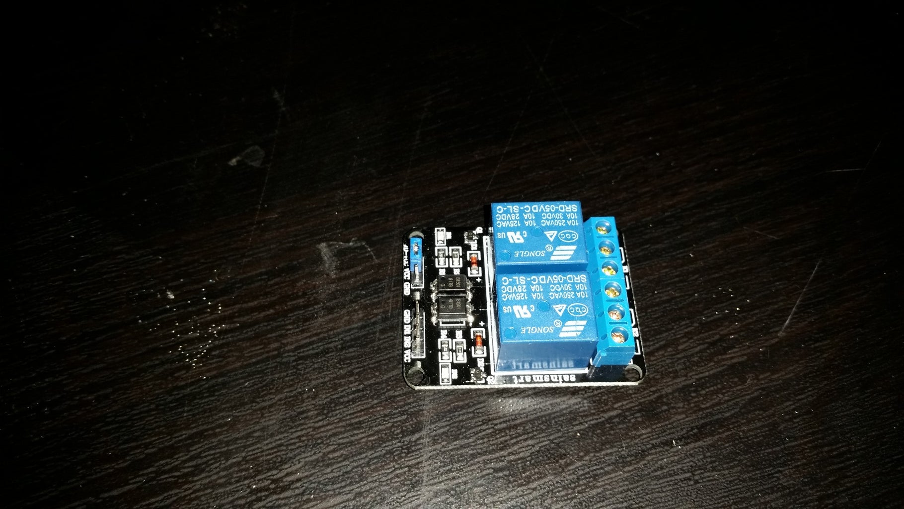
- A relay module board for the pi. They come with up to 8 channels, you can use as many as you have free controllable GPIO ports. I am using two, if you need more pins, refer to the diagrams found here http://wiringpi.com/pins/ and http://www.hobbytronics.co.uk/raspberry-pi-gpio-pi...
- I will be using pins that do not change between versions here, but the difference is important to note.
- The two following pages will help you identify your board
- Also note that I am using a 5v board, as is the case with most of the relay boards. However, there are 3v boards out there, if that is what you have, just make sure you change the power accordingly to the 3v pin. It is not a very popular option because the 3.3v on the pi is limited to 50ma, so it can take 1 MAYBE 2 relays of the 3v types, but as many 5v relays as the board can take.
- Last comment, these boards differ from bare relays (i.e. just buying a 50c relay), in that the board has built in protection circuitry so you do not damage your pi
- A raspberry pi(does not matter which one, but check the site above to make sure you are using the correct pin mapping.
- Wiring and the proper adapters. Ribbon cables are popular, in my case I had old speaker\fan\USB headder connectors from old computers that I just reused and spliced. Single pin header cables would be best.

- soldering iron (I like the cordless ones) if you are not using single pin wires\connectors and need to rearrange a few wires.
An 8th inch flat blade screwdriver for the relay board's screw terminals.
optional: Shrink tubing
and lighter so that you don't have exposed wiring or gunky electrical tape.
Step 2: Wire the Relay to the Board


We will be using pins 2 (5v), 6 (ground), 11, and 12. They are not side by side, and so I need to rearrange the cable a bit so it has the correct connectors. Also, note that 11 and 12 are the "header numbers" (physical location), but the wiringpi software that controls them calls them pins 0 and 1.
I am using 2 headers to plug into the pi, but still only the same 4 wires, so I snipped the wires that needed to go further and soldered them to the other connector.
The first step is to change it so that on the relay side, pins 1-4 of the connector need to co to a connector that is at least 3 wide and go in the holes 3-1 of the connector on the pi side (i.e. pins 2 and 6 on the pi since that is where the 5v and ground are). So the connector now has to do the following:
Pi 2 - relay 4
Pi 6 - relay 1
Meanwhile, pins 2 and 3 on the relay side are each sent to pins 11 and 12, so it can use a simple 2 wide connector.
Step 3: Connecting the Device to the Relay


In order to connect whatever you are controlling, you will have to cut a leg of the power so send it through the relay. If it is a device that uses only AC power, be careful, and if you can, use the hot as your on\off. If it goes to an DC adaptor (as the LEDs I will be using do), then cut on the DC side. This is much MUCH safer to operate. Cut the - line, so that even if there were some sort of short, there would not be any power going through it until you turn it on.
These relays do have 3 slots because there are 2 options. One is that it turns off when power is applied from the pi, and the other (more conventional use) is that it turns on when power form the pi is applied. Select the one that works for your use.
Step 4: Installation
First turn off your pi, connect everything in place, and then turn the power back on.
I am using wiringpi. Many builds come with wiringpi installed. To test this, use the commands
gpio -v
gpio readall
If it did not succeed, then try installing wiring pi. More information is provided on the wiringpi website http://wiringpi.com/download-and-install/
Step 5: Testing

We can now test the relay by sending the commands to turn them on\off.
First use gpio readall to see everything mapped out (useful to know, and good for diagnostics... more on that lower)
Second, assuming you used the same pins as me (otherwise look at your schematic and figure it out), use the commands gpio read 0 and gpio read 1 (this will read the states of pins 0 and 1). With my module, 0 is on, 1 is off.
Third, we want to change the pin mode. We want an out pin, not an in pin. The commands are gpio mode 0 out and gpio mode 1 out.
Lastly we want to actually use the pin, so we will send gpio write 1 0 (the first number is the pin number, the second number is the state).
If it turns on and off as expected, then you are done. If like me, you have some issues, the next step is to read back the pin you just wrote to. It turns out I have problems on my pin 1, and only my pin 0 worked properly. As it turns out, it is because my pin was still set to IN rather than OUT.
That's it, now you can use your devices via SSH terminals.
Step 6: Extra; Adding the On/off Command to Octopi

The code used to add an option to the octoprint web server is fairly simple.
First edit the file ~/.octoprint/config.yam I use nano so it goes
sudo nano ~/.octoprint/config.yaml
Then go down to actions and add the folowing (obviously naming it as you want)
-action: lights on
command: gpio mode 0 out; gpio write 0 0
name: lights on
-action: lights off
command: gpio mode 0 out; gpio write 0 1
name: lights off
I added the mode change for the off option as well just in case the pi were to reboot with the lights on but the mode to IN.
Enjoy!

Runner Up in the
Raspberry Pi Contest 2016

Participated in the
Digital Life 101 Challenge


