

Introduction: Controlling Arduino With Gamepad


Lately I've been curious about befriending Arduino or any other microcontroller with a gamepad in order to have physical interaction with the things I make, but there seemed to be no fast or cheap way to do so.
Most solutions involved:
- Completely dismantling your game controller and bypassing USB logic with some weird contraption made of wires, protoboards and a microcontroller acting as an UART gate, which then passes messages to HC-05 bluetooth module.
- Making your own joystick/gamepad based on the above principles
- Buying a microcontroller with USB-host functionality and writing a ton of code for USB driver to have a “puppy on a leash”
- Using a bunch of third-party software, like Input remapping programs, Processing IDE and Python to do this one simple thing
For quick testing of remote-controlled the prototype (most likely right on the desk or workbench) we need a simple solution with minimal expenses. This is why I've decided to do a little research in this topic and implement small, but somewhat useful software solution to this problem.
Over the course of development I found out that this material will not only be useful in this one particular application, but can also serve as a foundation for much wider range of applications, like data logging systems, PC-based flight control, remote sensor data acquisition etc. etc. etc.
Step 1: INTRODUCTION
The original article is published on my website. This is still work in progress and requires lots of fine-tuning, but that's what DIY is all about - continuous improvement!
The original amount of material I wrote is a bit too big for this Instructable, so in order to save you some time and save myself from repeating the same task over again I will skip some of the stuff and provide a link to an appropriate resource instead.
General concept of my project consists of the following:
- We are going to use a wired/wireless gamepad connected to PC
- We will implement a lightweight software written in C++ in order to read the current state of XInput Device(gamepad)
- If necessary, we can transform current gamepad state into short useful data sequence (button state, axis position etc.), which will be sent over UART to our microcontroller.
- Optionally, we can read some data back from microcontroller, like Force-Feedback triggers for gamepad, or plain-simple sensor data.
These principles will also help us to develop the basis for a two-way communication between Arduino(or any other MCU) and a PC, which we can use, for example, for a low-resolution serial camera feed or almost real-time sensor information update.
The main advantages of this method are:
- It does not require any hardware modifications, like torturing the gamepad
- It will not cost you a penny, given that you have a computer and some means of serial communication( like USB-UART interface, HC-05/06 module etc.)
- In this specific situation it will work on any Windows-powered PC with any XInput compatible gamepad (which includes cheap rumblepad/sixaxis clones)
However, it requires at least some basic C++/Arduino programming skills and a little bit of technical know-how.
Step 2: LEARNING SERIAL COMMUNICATION
Before we dive into development process, I'd like you to go over some preliminary reading in order to understand what we are trying to do. I've already compiled a simple tutorial on serial communication (second link), so once you are done, we can start developing a fully functional program to suit our purposes.
READING MATERIALS:
We will start with creating 2 simple functions, which will allow to open and close UART connection.
For this you'll need MS Visual C++, pair of hands and caffeine-infused brain.
The COM port initialization is a straightforward process: first we create port configuration portDCB, which contains all the communication settings, and then we assign the port handle. Notice, that port is initialized with CreateFile() function call, and just like with conventional files we can use ReadFile() and WriteFile() to exchange data.
Then we assign the new configuration with SetCommState() function call. If at any step of this process we encounter an error, we will print the appropriate message and return FALSE.
Otherwise, we return TRUE and as a result of execution of UART_Init(), port variable will now point to a serial port handle.
For the purpose of flexibility we will provide the COM port name and its baud rate as arguments of this function. Default settings are set to 8 bit transmission length with 1 stop bit. Parity, error correction and any type of flow control are disabled by default.
/*
 * UART_Init()
 * Opens the com port with ID "portName" at baud rate "baud"
 * HANDLE *port becomes a pointer to an active COM port connection
 * Returns whether the connection is successful or not.
 */
BOOL	UART_Init(HANDLE *port, LPCWSTR portName, DWORD baud)
{
	DCB portDCB;	      // _DCB struct for serial configuration
	bool result = FALSE;  // Return value
	COMMTIMEOUTS comTOUT; // Communication timeout
	*port = CreateFile(portName, GENERIC_READ | GENERIC_WRITE, 0, NULL, OPEN_EXISTING, FILE_FLAG_WRITE_THROUGH, NULL);
	// Try opening port communication
	if(*port==INVALID_HANDLE_VALUE)
	{
		wprintf(L"ERROR: Cannot open port %s\n",portName);
		return FALSE;
	}
	// NEW SETTINGS
	portDCB.DCBlength = sizeof(DCB);// Setup config length
	GetCommState(*port, &portDCB);	// Get default port state
	portDCB.BaudRate = baud;	// Set baud rate
        portDCB.fBinary = TRUE;		// Enable Binary mode
        portDCB.fParity = FALSE;	// Disable parity
        portDCB.fOutxCtsFlow = FALSE;	// No CTS
        portDCB.fOutxDsrFlow = FALSE;	// No DSR
        portDCB.fDtrControl = DTR_CONTROL_DISABLE;	// No DTR
        portDCB.fDsrSensitivity = FALSE;	// No DSR sensitivity
        portDCB.fTXContinueOnXoff = TRUE;	// TX on XOFF
        portDCB.fOutX = FALSE;			// No XON/XOFF
        portDCB.fInX = FALSE;			//
        portDCB.fErrorChar = FALSE;		// No error correction
        portDCB.fNull = FALSE;			// Keep NULL values
        portDCB.fRtsControl = RTS_CONTROL_DISABLE; // Disable RTS
        portDCB.fAbortOnError = FALSE;	// Disable abort-on-error
        portDCB.ByteSize = 8;			// 8-bit frames
        portDCB.Parity = NOPARITY;		// Parity: none
        portDCB.StopBits = ONESTOPBIT;		// StopBits: 1

	// Try reconfiguring COM port
        if (!SetCommState (*port, &portDCB))
        {
          wprintf(L"ERROR: Cannot configure port %s\n",portName);
          return FALSE;
        }

        /// Communication timeout values
        result = GetCommTimeouts(*port, &comTOUT);
        comTOUT.ReadIntervalTimeout = 10;
        comTOUT.ReadTotalTimeoutMultiplier = 1;
        comTOUT.ReadTotalTimeoutConstant = 1;
        /// Set new timeout values
        result = SetCommTimeouts(*port, &comTOUT);
        return TRUE;
}
Closing COM port is very easy. All we need to do is release the handle (line 2) and set *port pointer to NULL, so we accidentally don’t access the old handle.
UART_Close() function returns FALSE if we are trying to close an uninitialized or previously closed port handle.
BOOL UART_Close(HANDLE *port)
{
    if (*port == NULL) return FALSE;
    CloseHandle(*port);
    *port = NULL;
    return TRUE;
}
As you've already guessed, the next logical step will be implementing functions to send/receive UART messages. The key moment of this part is that we will use communication events, described in MSDN article mentioned earlier.
BOOL UART_Send(HANDLE port, char *Buffer)
{
	DWORD bytesTransmitted;
	if(!WriteFile(port,Buffer, strlen(Buffer), &bytesTransmitted, NULL))
	{
		DWORD Errors;
		COMSTAT Status;
		ClearCommError(port,&Errors,&Status);
		printf("ERROR: Unable to send data.\n");
		return FALSE;
	}
	else
	{
		return TRUE;
	}
}
Assuming that our arduino might be occupied at the time of transmission and could not provide a proper response, we want to wait for EV_RXCHAR event to occur every time RX has incoming data. To address this problem we will set up a communications mask and wait for our event before reading the next byte.
BOOL UART_Receive(HANDLE port, char *Buffer)
{
	DWORD bytesTransmitted = 0;		// Byte counter
	DWORD status = EV_RXCHAR;		// transmission status mask

	memset(Buffer, 0, BUFFER_SIZE);		// Clear input buffer

	SetCommMask (port, EV_RXCHAR);		// Set up event mask
	WaitCommEvent(port, &status, 0);	// Listen for RX event

	if(status & EV_RXCHAR)			// If event occured
	{
		DWORD success=0;
		char c = 0;
		do
		{
			if(!ReadFile(port,&c, 1, &success, NULL))	// Read 1 char
			{
				// If error occured, print the message and exit
				DWORD Errors;
				COMSTAT Status;
				ClearCommError(port,&Errors,&Status);	// Clear errors
				memset(Buffer, 0, BUFFER_SIZE);		// Clear input buffer
				printf("ERROR: Unable to receive data.\n"); // Print error message
				return FALSE;
			}
			else
			{
				Buffer[bytesTransmitted]=c;	// Add last character
				bytesTransmitted++;		// Increase trans. counter
			}
		} while((success==1) && (c!='\n'));		// do until the end of message
	}
	return TRUE;
}
These four functions should be enough to handle basic UART communication between Arduino and your PC.
Now, let's evaluate the functionality of our code with a simple UART loopback test. We need to finish the program's _tmain() function first:
int _tmain(int argc, _TCHAR* argv[])
{
    HANDLE port;
    char   Buffer[BUFFER_SIZE] = "TEST MESSAGE\n";

    // Unable to open? exit with code 1
    if (!UART_Init(&port, L"COM8:", CBR_115200))
    {
	system("PAUSE");
        return 1;
    }
    // : continue execution
    else
    {
	// Here we send the string from buffer and print the response.
	// Our Arduino loopback should return the same string

	int msgs = 0;	// reset # of messages
	while((port!=INVALID_HANDLE_VALUE) && (msgs<100))	// Send/Receive 100 messages
	{
		printf("Sending: %s\n", Buffer);
		UART_Send(port, Buffer);				// Send data to UART port
		if(UART_Receive(port, Buffer))				// Receive data
			printf("Received: %s\n", Buffer);
		PurgeComm(port, PURGE_RXCLEAR | PURGE_TXCLEAR);		// Flush RX and TX
		msgs++;							// Increment # of messages
	}
        UART_Close(&port);						// Close port
    }
    system("PAUSE");
    return 0;
}
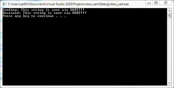
This code initializes port COM8, which is my USB-UART cable (don't forget to change that part to your port #). Then, it sends 100 messages over UART and prints both original message and response. Implementing the communication event listener earlier really paid off at the end. If you look at this program carefully, you'll see that we have only used about a dozen lines of effective code to make it work!
Now, let's setup our Arduino to work as UART loopback device. We will also implement an event-driven UART communication in order to be able to do some other stuff while not transmitting.
Open up your Arduino IDE and use this code as an example:
String buffer = "";         // a string to hold incoming data

void setup() {
  buffer.reserve(255);     // Reserve 255 chars
  Serial.begin(115200);    // Initialize UART
}

void loop() {
    // NOP
}

// SerialEvent occurs every time we receive RX interrupt
void serialEvent() {
  while (Serial.available()) {
    char c = (char)Serial.read();  // Read character
    buffer += c;                   // Add it to buffer
    // If end-of-line, reset buffer and send back the data
    if (c == '\n') {
      Serial.print(buffer); // Loopback
      buffer = "";          // Clear buffer
    }
  }
}
Now you can upload the sketch to Arduino, compile the C++ project and test it!
Step 3: GETTING INPUT FROM GAMEPAD
Now, that we know how to send the information to Arduino, we only need to learn how to acquire input from the XBOX gamepad.
In this section we will learn the basics of XInput and write a very simple program, which displays current gamepad state in the console output. We will also learn some important aspects of pre-processing the input values to avoid problematic thumbstick input ranges ("dead zones").
THE BASICS
XInput API provides the means of getting input from XBOX 360 controllers and includes a variety of tools to set the controller effects(farce feedback), process audio input/output for gaming headsets and do other cool stuff.
XInput supports up to 4 controllers, but in our situation only controller #0 will be used as default.
In order to update the current state of the gamepad we will use XInputGetState() function. It takes 2 parameters: the gamepad ID(which is 0 in most cases) and the pointer to XInput state variable. The return value of XInputGetState can be used to check the availability of the gamepad. The value of ERR_SUCCESS means that the gamepad is on, and XInput state now has it's current state.
XINPUT_STATE consists of the following elements:
typedef struct _XINPUT_STATE {
  DWORD          dwPacketNumber;
  XINPUT_GAMEPAD Gamepad;
} XINPUT_STATE;
dwPacketNumber indicates whether the gamepad state has changed.
Gamepad is a data type, which represents current gamepad state, including thumbstick positions, trigger values, D-pad and button flags.
typedef struct _XINPUT_GAMEPAD {
  WORD  wButtons;
  BYTE  bLeftTrigger;
  BYTE  bRightTrigger;
  SHORT sThumbLX;
  SHORT sThumbLY;
  SHORT sThumbRX;
  SHORT sThumbRY;
} XINPUT_GAMEPAD;
sThumbLX, sThumbLY, sThumbRX and sThumbRY are 16-bit signed integers, which take values from −32,768 to 32,767. These correspond to current thumbstick positions.
bLeftTrigger and bRightTrigger take values in 0..255 range.
wButtons represents the state of all buttons on an XBox controller, where each bit corresponds to current state of each individual button. If we want to check whether the X button was pressed we need to perform the following operations:
XINPUT_STATE gpState;	                 // Create state variable
memset(&gpState,0,sizeof(XINPUT_STATE)); // Reset state
DWORD res = XInputGetState(0,&gpState);  // Get new state
if(gpState.wButtons & 0x4000 )
{
	printf("Xplosive kick!\n");
}
The following list shows all buttons and their corresponding bitmasks:
XINPUT_GAMEPAD_DPAD_UP              0x0001
XINPUT_GAMEPAD_DPAD_DOWN            0x0002
XINPUT_GAMEPAD_DPAD_LEFT            0x0004
XINPUT_GAMEPAD_DPAD_RIGHT           0x0008
XINPUT_GAMEPAD_START                0x0010
XINPUT_GAMEPAD_BACK                 0x0020
XINPUT_GAMEPAD_LEFT_THUMB           0x0040	// These are thumbstick buttons
XINPUT_GAMEPAD_RIGHT_THUMB          0x0080
XINPUT_GAMEPAD_LEFT_SHOULDER        0x0100	// Left bumper
XINPUT_GAMEPAD_RIGHT_SHOULDER       0x0200	// Right bumper
XINPUT_GAMEPAD_A                    0x1000
XINPUT_GAMEPAD_B                    0x2000
XINPUT_GAMEPAD_X                    0x4000
XINPUT_GAMEPAD_Y                    0x8000
LET'S PRACTICE
At this point we have all the tools we need to write our first program with XInput. It will be laughably simple, but it will help to understand how this process works and which elements of XInput we need.
#include "stdafx.h"
#include <Windows.h>
#include <XInput.h>

#pragma comment(lib, "XInput.lib")	// required for linker

int _tmain(int argc, _TCHAR* argv[])
{
	XINPUT_STATE gpState;	// Gamepad state
	int player = -1;	// Gamepad ID

	// Polling all 4 gamepads to see who's alive
	for(int i=0;i<4;i++)
	{
		DWORD res = XInputGetState(i,&gpState);	// Getting state
		if(res==ERROR_SUCCESS)			// If alive - print message
		{
			printf("Controller #%d is ON!\n",i+1);
			player = i;	// Assign last alive gamepad as active
		}
	}
	if(player<0) // If player==-1 in other words...
	{
		printf("Haven't found any gamepads...\n");
	}
	else
	{
		while(true)
		{
			system("CLS");					// Clear screen
			memset(&gpState,0,sizeof(XINPUT_STATE)); 	// Reset state
			DWORD res = XInputGetState(0,&gpState);		// Get new state
			printf("LX\tLY\tRX\tRY\tLTrig\tRTrig\tButtons\n"); // Print header

			// Thumbstick values are divided by 256 for better consistency
			printf("%d\t%d\t%d\t%d\t%d\t%d\t%d\n",
					gpState.Gamepad.sThumbLX/256,
					gpState.Gamepad.sThumbLY/256,
					gpState.Gamepad.sThumbRX/256,
					gpState.Gamepad.sThumbRY/256,
					gpState.Gamepad.bLeftTrigger,
					gpState.Gamepad.bRightTrigger,
					gpState.Gamepad.wButtons);
		}
	}
	system("PAUSE");
	return 0;
}
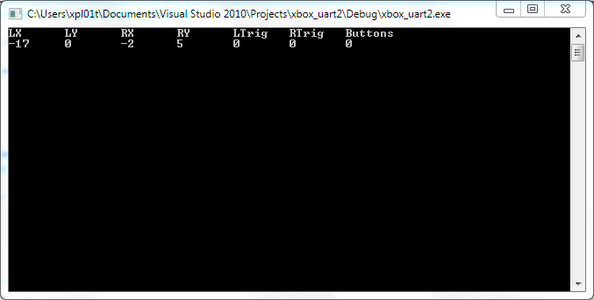
Once you build the solution and run your program, you will see the output changing when you move thumbsticks, or push buttons on your gamepad. We will send this data to Arduino board in the next section of this tutorial.
Right now I want you to pay attention to the output, when you are not doing anything. Values of LX, RX, LY and RY are not equal to 0, as we expect them to. This happens for a number of reasons, but what matters most is that we are aware of this phenomena!
These fluctuations and inconsistencies in values are called "dead zones". To get rid of this nasty anomaly we need to find the lowest marginal value at which we can consider that the thumbstick is actually pushed in some direction.
To do so we need to define a deadzone threshold and compare it to current values. Check out MSDN reference for more info.
Meanwhile, use this sample code to correct these values:
float LX = gpState.Gamepad.sThumbLX; // Get LX
float LY = gpState.Gamepad.sThumbLY; // Get LY
magnitude = sqrt(LX*LX+LY*LY);	     // Calculate the radius of current position
if(magnitude < XINPUT_GAMEPAD_LEFT_THUMB_DEADZONE) // Inside dead zone?
{
	// Set all to 0
	LX=0.0;
	LY=0.0;
}
// Do the same for RX and RY
There are also predefined dead zone values for left and right thumbsticks and triggers. You can use these, or define your own thresholds(in my case ~6500 worked for left and right stick), but remember that these values largely depend on how beat-up your gamepad is!
#define XINPUT_GAMEPAD_LEFT_THUMB_DEADZONE  7849
#define XINPUT_GAMEPAD_RIGHT_THUMB_DEADZONE 8689
#define XINPUT_GAMEPAD_TRIGGER_THRESHOLD    30
ADDITIONAL READING
The only additional resource I'm going to mention is this one: XInput Game Controller APIs
It has everything you need to know about XInput, including complete reference and helpful programming guide.
That's it for this part. Now, let's try to combine our skills in programming gamepads and serial connections to control Arduino remotely!!! ...in case you forgot where we started...
Step 4: PUTTING PIECES TOGETHER
If you fully understood all the materials in previous steps, you should be able to write an XBox controller-to-UART interface or implement PC-Arduino communication on your own.
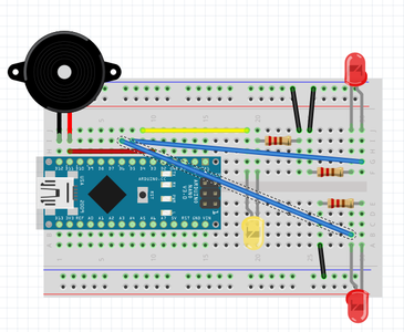
As a final example I will use a very simple contraption: an Arduino with few LEDs and the buzzer.
Originally I wanted to build a small RC car, but due to lengthy delays in parts delivery I won't be able to do it at least for another week or so... If you have a pair of EasyDriver boards you could connect direction pin instead of yellow LED, and motor step pin instead of red LEDs(see schematic above). A piezo-buzzer connected to pin D3 reacts on any button press on your controller.
The entire functional description boils down to this:
- Read the XBox controller state and transform it into a short, but well defined string.
In my case I'm only sending motor speeds, direction and button state, so the message looks like this:
LLL RRR D BBBB
where LLL is the Left Motor speed, RRR is the Right Motor speed, and BBBB represents button state.
D is a motor direction, which takes only two values: 1 for forward and 0 for backward.
Both LLL and RRR will be normalized for deadzones and scaled to smaller values (under 255)
Alternatively you can send raw XINPUT data to arduino and process it on the microcontroller itself. - Next, we send this message over UART to Arduino
- Set all motor speeds to acquired values and check button state to determine additional actions
- Send some data back to PC (I'm just sending motor speeds for debugging)
- Acquired data is processed into some visual representation. Use anything you like, be it a simple text output in console window, or GUI-based output, like progress bars, graphs, flowcharts or even OpenGL rendering.
We've already learned how to read UART messages using events, so we don't really need to worry about proper timing. PC-side code can be further improved with such cool things, like multi-threading and asynchronous communication, but we won't be doing that today.
So, let's start with Arduino.
Attached is a simple sketch for our RC car. Nothing special, just setting motor speeds depending on thumbstick position.
sqrt(LX*LX+LY*LY) sets the magnitude of motor speed
LY sign(- or +) controls the movement direction (forward / backward).
Based on the value of LX we set the difference between Left and Right motor speed. If LX is positive, then Left motor is set to current speed value, and Right motor uses(128-LX). If LX is negative, we assign values the opposite way.
On PC side I've created a small class, called XBoxUart, which combines all the things we've learned previously in a single program.
Please, use links below to download the source code for PC and Arduino side.
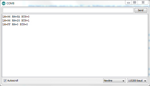
First, upload the arduino sketch. You can test if it's working by opening a Serial Monitor at 115200 bod and sending data manually. For example message "100 100 1 0" is an equivalent of moving forward 100 steps(left and right motors) with no buttons pressed. In response you should get strings, shown in the screenshot above.
NOTE: Don't forget to change the COM port name to whatever your Arduino CDC is. If you have an HC-05 module, you can connect it directly to Arduino RX and TX pins, if you wanna try it without wires.
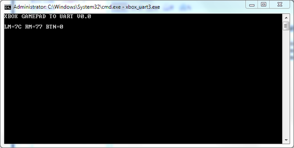
Now you can compile the C++ code in Visual Studio, start your XBox controller, launch the program on your PC and see how LEDs(or motors) change their behavior with movement of the thumbstick! Pressing any button will trigger the buzzer. The output in the console window will be similar to what you see on the last screenshot.
Attachments

Step 5: AFTERWORDS

Thank you for your attention and I hope this material will help you in the future projects.
This article is a simple and very crude example of how to control things over UART, but in the near future I will try to make a more flexible solution.
You can check my blog for updates: http://mygeekblog.net
If you like this article, please cast your vote for my "Coded Creations" entry.
Regards,
Anton.

Participated in the
Automation Contest

Participated in the
Coded Creations


