

Introduction: Controlling a Relay Board With an Arduino Uno


In this instructable we will control a Velleman K6714 relay board with an Arduino. The beauty of using relays is that we can use a modest little Arduino to switch household appliances or what you may have. The Velleman K6714 has been around for more than a decade and lets us switch up to 16 relays. There's several ways to construct a K6714, but in this instructable we'll use the one I DIY'ed a few years ago which does not have the ULN8023 transistor array. We need to make a bridge between the 5V output of an Arduino digital out and the connectors of the K6714 relay board.
Step 1: What You Need
Hardware:
- Velleman K6714 or K6714-16 board.
- Arduino Uno.
- Bread board with a bunch of wires.
- 2N2222 transistor (2N2222A is also perfect).
- 5K6 1/4 W resistor (green blue red gold).
Software:
- Arduino IDE.
NB: The K6714 has 8 or 16 relays. If you want to switch more than one relay, simply repeat the circuit for other digital out pins from the Arduino. You'll need an extra 5K6 resistor and 2N2222 transistor for every relay you want to switch.
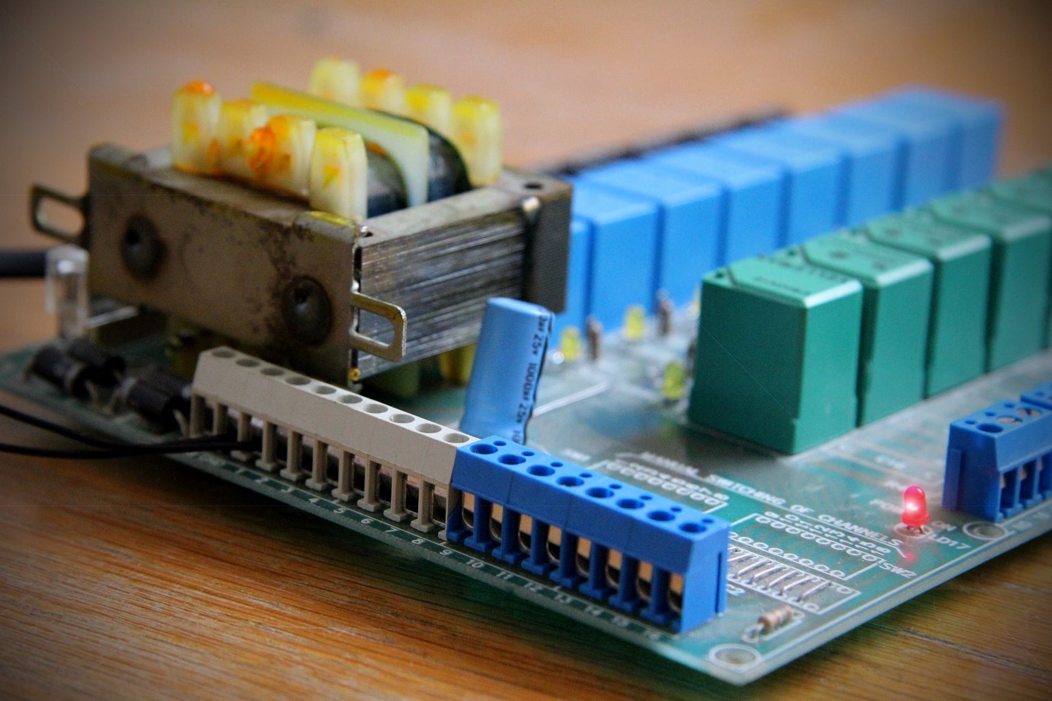
Step 2: Examining the K6714 Relay Board


The Arduino site already explains how to switch a relay, but it assumes the relay needs to be powered as well. In the case of the Velleman K6714, the switching connectors are already powered and the relays already have a diode connected to them. We measure 18 V between the GND and any of the 16 connectors. 62 mA go through the circuit when the relay is switched on. If we use a 2N2222 transistor (a very common general purpose switching NPN transistor), we have a beta of at least 100. So the Arduino needs to put at least 62 mA / 100 = 620 uA through its circuit that switches the base of the 2N2222. Assuming the digital out of the Arduino has a 5 V output and the 2N2222 uses .7 V, we are left with a resistor that has 4.3 V potential difference and 620 uA current, so Ohm's law dictates it then has a resistance of 4.3 V / 620 uA = 6900 Ohm. We'll round it down to make sure the transistor switches the relay to a 5K6 resistor.
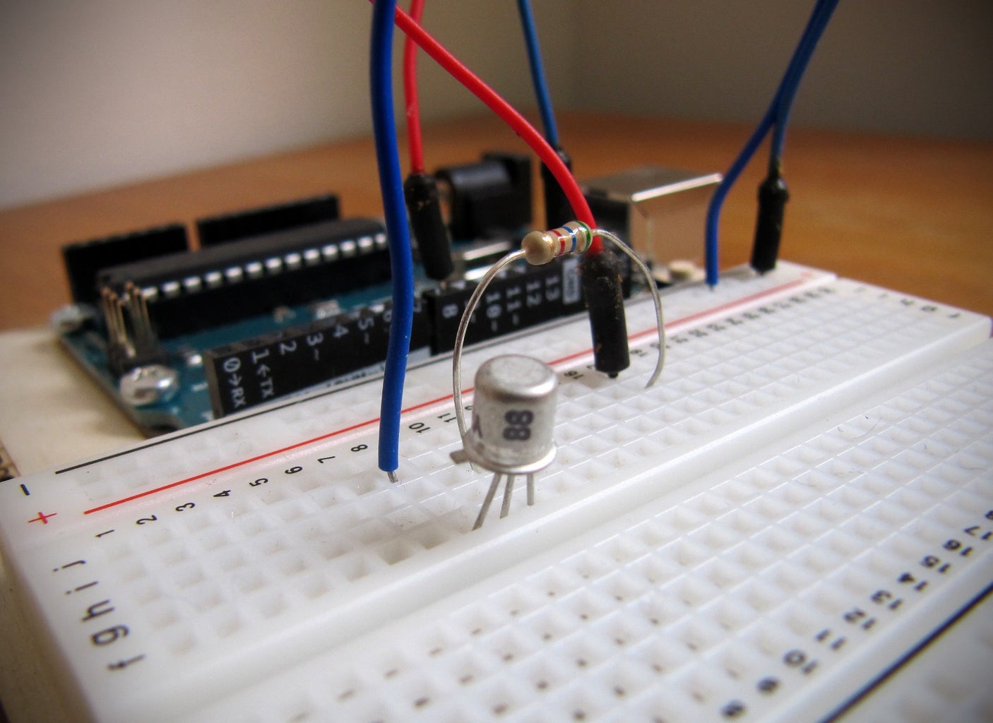
Step 3: The Circuit


Step 4: Arduino Code
/*
Arduino Uno digital pin switching a Velleman K6714 relay board.
http://www.velleman.eu/products/view/?country=be&lang=en&id=345892
Digital pin switches a 2N2222A NPN transistor.
Hens Zimmerman, hz37@xs4all.nl, June 16, 2015.
*/

const int relayPin = 8;

void setup()
{
  pinMode(relayPin, OUTPUT);
}

void loop()
{
  digitalWrite(relayPin, HIGH);
  delay(1000);
  digitalWrite(relayPin, LOW);
  delay(1000);
}
Step 5: Finished

So there you have it, a finished relay switcher. If you want to use this as a standalone solution, do know that you can power the Arduino from the K6714 as well. It has a spare VB pin connector that's well within the limits of the Arduino Uno input voltage (i.e. 6 - 20 V).
Happy switching!


