

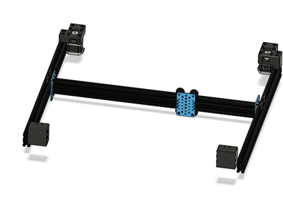
Introduction: CoreBot V2 Large Format CoreXY 3D Printer


Here I present you the new version of my large format CoreXY 3D printer known as CoreBot. The main goal was to make the built more affordable, easier and cheaper to built.For this reason the linear rails were replaced by rollers in an aluminium profiles. These were provided by Allgäutec.
The printer was developed in collaboration with Allgäutec to get the most performance out of the motion components.Some of the electronics were provided by CR3D. The machine I buillt has a built volume of 410x410x410mm (otherwise it would not fit trough my door).
From the rigidity of the frame and motion components I'd trust the system up to 650x650mm with reasonable speeds in xy direction. For Lager Sizes you need to change over to 15mm belts.Main Features:
- Large Built Volume- budget-friendly (relativly)
- Frame Built from 2040 Extrusion with blind Corner Connections (similar to Voron)
- Open Source- Triple z axis for automatic bed leveling
- 10mm belts for xy Motion- drag Chain for XY-Gantry
- sensorless homing
- 12mm Cast Aluminium bed- 2000W 230VAC Silicone Heate
- magnetic removeable builtplate
- Duet 3 6HC Controller (Others possible)
- Duet 7" Touchscreen
- E3D V6 or E3D Volcano Hotend (Up to 1.2mm nozzle size)
- Bondtech Dual Drive Gear Extruder- Inductive Probe for Bed Leveling
Modular Design:
The printers design was kept mostly simple so it can be adapted to your needs. The design an parts I used are tailored to what I am comfortable with. If you have any other ideas on what you want to see on the machine feel free to design and share it with the community. You can also ask me to design something but my time is limited.
Supplies
If there are any problems during the assembly:
- Refer to the .step, .iges or Fusion360 Files
- ask away in the comments - maybe others have similar problems
Step 1: CAD Model and Source Files
I built the printer completely using Autodesk Fusion 360. I exported the machine in .stp and .iges format for people who use other CAD-Systems.
For everyone who does not want to deep dive into CAD themselves there is the Fusion360 Model available through this link:
Fusion 360 Model of CoreBot V2
The model can be viewed in most modern browers as well as the Fusion 360 app.

Step 2: Parts and Files
Printed parts / STL Files:
The printed parts are uploaded here. For user mods also look at:
- Thingiverse
- Prusaprinters
BOM:
Due to modular design of the BOM contains the parts I used for my Built. Espacially the parts Like Display, Controller, Hotend, Bed Leveling Sensor & Extruder are very easy to change and adapt from different Machines.
Step 3: Frame Assembly
Frame Assembly ist pretty straight forward.
First Tap all horizontal extrusion profiles using a M5 tap (each horizontal xy extrusion needs to be tapped 4 Times). If you want to use feet or rollers for the printer drill the appropriate holes into the vertical extrusion. Also tap both ends of bed y and x-axis extrusion.
You also have to Drill the access holes for the screws in the vertical z Extrusion. On the top and bottom and each Extrusion needs a total of 4 holes. The 2 front z extrusions need 2, the Back 4, additional holes at height of the xy Stage. Use the Template to find the right position, you may refer to the drawings as well. Additionally Drill the two holes in the Center of the Bed x Extrusion for assembly.
The assembly has to be done on a smooth and even surface to ensure the frame is square. Use a square in addition to be sure everything is Assembled correctly.Start with the 4 bottom and 4 vertical extrusion profile, connecting each set of profiles using 2 M5x12 Button Head screws. You can tighten the screws through the holes previously drilled. Afterwards Install the 3 horizontal profiles for the xy Gantry. At last at the 4 top Extrusion profiles.
Measure the diagonals of each side of the frame to ensure, everything is square.
The frame is complete now.

Step 4: Z-Stage
The z-Stage consists of 3 Sets of Spindles and smooth rods. The assembly of these 3 pieces is nearly identical.First install the pillow bearings in the bottom motor holders. Then mount these to the frame. The front mounts are mounted adjacent to the vertical extrusion, the Back one has to be in the Center of the Back bottom extrusion.Now Install the 608 bearings in the top mount of the z-spindles.
Front z-assembly:
Push the 12mm smooth rods in the Front Motor mounts. Attach the Spindles to the pillow Block. Attach the 36 tooth pulley to the Spindle and Slide on the closed Loop belt.Slide on the z-carriage. Put on the leadscrew nut and LMK12LUU bearing. Attach both to the z-carriage. Install the top Spindle mount on both Front z-axis.Attach the Bed x Extrusion to the z-carriages.
Back z-assembly:
Push the 12mm smooth rods in the top z-mounts. Slide the trapezoidal Spindle into there as well. Slide the Nut and the LMK12LUU bearing on. Attach the Back z carriage to the Nut and LMK12LUU. Slide the closed Loop belt and the 36 toothe pulley on the Spindle.Push everything into the bottom Back z Motor mount. You might have to loosen the Back Extrusion of the xy Gantry to get everything in. Secure the z top mount to the frame.Now Install the Bed y Extrusion. First mount it to the bed x Extrusion using two M5x12 screws you Access through the holes drilled in the bed x Extrusion. Make Sure Bed x and y Extrusion are perpendicular and centered. Now move the bed y Extrusion into the back z carriage. Make Sure Everything stays square / perpendicular. Maybe you have to adjust the Position of the Back z top and bottom mount a little bit. Mount the z-back-carriage to the bed y Extrusion using 6 M5 screws. Make sure you don't apply force to the spindle so you Bent it while tightening the Back screws. If your Bed y Extrusion is slightly to Long, Cut it a few mm, if it is to short, add some spacers or washers in between the z_back_carriage and the bed y Extrusion (See Picture).Lastly fix the 36 tooth pulley to the Back z Spindle.
Z steppers:
But the 24 tooth pulleys onto the 3 steppers, install Them in the z-Motor-mounts and tighten the closed Loop belts while doing so.
Step 5: XY Stage (CoreXY)


First mount the xy stepper motor mounts and xy idler mounts to the frame. Insert 2 25 Teeth (toothed idlers) into each xy idler mount. Slide the 25 Teeth pulleys onto the Nema17 xy steppers and mount them to the xy_stepper_mounts. Do not tighten the pulleys completely now, they may need to be adjusted after installing the belt.
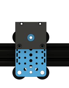
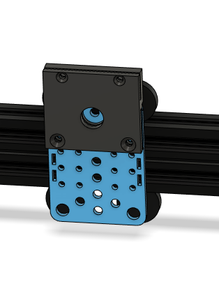
Prepare the 3 motion plates. The plate for the x-carriage has to get 2 M4 holes tapped to later attach the belt clamp to it.
Slide the x-carriage onto the x-extrusion for the gantry. Then mount the two y-carriages on both sides using M5x12 button head screws. Loosen up 2 screws on each side of the x-axis to be able to install them in the frame. Make sure the gantry moves freely. Move it to front and back, left and right multiple times. If it binds up somewhere re-adjust the excentric nuts on the carriages. If this does not help, check if your frame is squre.
Add the XY_Joiners to the x-axis. The distance between the y-carriage-plate and the xy-joiner should be about 16mm. Insert the Idlers into the xy-Joiners. Each side should get 1 toothed idler and 1 smooth idler. On the left side the smooth idler goes in on the bottom, on the right side it is on the top.
Route through the GT2 10mm belts. Attach them to the x belt clamp with loose tension (yeah...tight but not to tight). For final belt tensioning we will use the slots in the stepper motor mounts. Mount the belt clamp to the x-carriage using 2 M4x10 countersunk screws.
Add 4 theaded inserts into the x-carraige dragchain mount. Mount the x-dragchain mount to the x-carriage using 2 M3x16 screws. You may install the dragchain now as well.
Assemble the BMG reforged extruder designe by Gavitka:
I slightly modified the design to mount it to the machine using 2 M5x10 screws.
Step 6: Electronics Assembly


First we will start with the 230V (AC) electronics compartment. I will not go over wiring these parts. If you are not sure on how to wire this on your own ask a professional for help. This kind of voltage may kill you if handled wrong!
Bottom Electronics Compartment (AC):
First mount the PSU to the PSU Mount Bracket (printed part). After that mount the PSU & SSRS to the frame of the printer - do not tighten them yet, the position will be adjusted later on. Attach the 24V and AC Cables to the PSU now.
Wire up the IEC connector and put it into the Bottom_IEC_Mount. Put it in position, it will be fixed while installing the top cover. Add the Electronics Base Mount to the frame. Do not forget to add a total of 4 M3 threaded inserts into the piece bevor installing it.
Add the bottom electronics panel and secure it to the Electronics Base Mount and PSU.
Add 4 M3 threaded inserts into the Bottom_FanMount. Attach a 4010 axial fan to it and wire up the fan directly to the PSU. Mount the Bottom_FanMount to the electronics Bottom Plate using M3 screws.
Wire up the signal wire up everything towards the Controller and the heated bed (I have used a connector on the bed side to make it a little easier).
Make sure, everything is tidy in the compartment and install the electronics top plate. Make sure no wires are pinched. Guide the 24V wires, thermistor cables and signal wires for the SSRs through the hole close to the extrusion. The 230V and Thermistor cables towards the bed go through the large hole.
Controller (DC):
The enclosure I used for the printer is a modified version of the great design posted by Narasak Mansurang on PrusaPrinters:
https://www.prusaprinters.org/prints/40686-compact...
If you like it give him a like. I have modified it to mount it to Slot 6 2020 / 2040 extrusion profile.
First mount the enclosure to the frame using M3 screws and t-nuts. There is place for 2 40mm fans for cooling the stepper drivers. This printer uses Nema17 steppers so it is not necessary to actively cool the board - convection cooling will be sufficient. If you add an enclosure definetly use the 2 cooling fans for the Duet 6HC.
Depending of the length of your stepper motors you might need to use a spacer in between the top extrusion and the enclosure.
You can add the dragchain mount now as well. Add 2 M3 threaded inserts on the back side of the piece to to attach the dragchain later on.
Mount the Duet 6 HC inside the control board.
For wiring everything up refer to the attached picture. After wiring & testing everything add the top lid.
Attachments
Step 7: Community Modifications
If I find the time I'll list all user modifications here:
MGN12H Conversion + E3D Hemera + Super Volcano mount by me


