

Introduction: Creating a Part Profile From an External Image


While working on a frame and panel front desk for an apartment building lobby, I ran into a problem. The architectural drawing called for several different moldings. I thought it would be easy. I checked out the web sites and found that one Company A had an AutoCAD drawing for each molding. Company B had an Adobe PDF. Company C had a paperback book of moldings, $28 at Amazon, but no other drawings. But since we only needed a couple of shapes, the only thing they could do was to trace the samples and fax them to us.
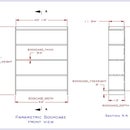
You can see that only height and width are given for molding, because that is all builders are really concerned with. A bit of the molding face is shown to help designers.
The same procedure will work for just about anything you want to trace.
Note: This instructable is for Alibre users and assumes that you are familiar with Alibre basics. If you are not I recommend that you work through the tutorials. They are very easy to follow and will have you up to speed in no time.
Attachments

Step 1: Capture the Image.

We will use Molding #261. There are several ways to save an image. I have my personal favorite, Gadwin PrintScreen is set up to allow me to drag a box around the image I want and save it as a JPG. It really doesn’t matter how you save it as long as Alibre supports it.
This is from Alibre Help: “Several popular file types are supported: JPG, GIF, TIF, BMP, DIB, RLE, EMF, WMF, PNG, JPE, JPEG, JFIF and TIFF. Alibre Design does not support JPEG 2000 or lossless JPEGs, as well as some types of TIFF files.”
Step 2: Insert an Image in a Drawing.

Open Alibre Design, select New Drawing, select Blank Sheet (A Landscape (11x8.5 inches) and check Create Empty Drawing box. Ignore Default View Scale, we will scale it later. Once the drawing is opened make sure that the dimensions are set to decimal inches. This will make it easier and more accurate to scale.
Make sure that New Sheet<1> is highlighted in the Drawing Explorer column. From the Insert menu, select Image. The Select Image dialog box appears. Browse to the saved location of the image you want to insert. Click the image’s file name. Click Open. The floating image appears in the drawing workspace and the mouse pointer has changed to a dotted crosshairs icon. Click the crosshairs icon on the drawing sheet to place the image near (but not on) the lower-left corner of the image. The lower-left corner represents the origin position on a part or assembly. This image placement will help us later.
Save the Drawing as Molding_261 (Alibre will add the file extension .AD_DRW when you click Save).
Step 3: Determing the Image Size.

The part of the molding that we care about is the profile (the gray face). If you recall your high school drafting class, the vertical and horizontal lines on the leading face of the profile are true-length lines. That means that after we have scaled the image the bottom edge will be 7/8" and the left edge will be 7/16". Then it will be straight forward to find the dimensions of the other parts.
Activate 2D sketch, and select Line. Draw a horizontal line just below the bottom line. To make it easy to see, use the crosshairs to help you. Dimension the line then exit sketch mode.
HINT: Sometimes image lines can be very wide and it is hard to decide where to begin the line. That was the case here. I had thin crosshairs and wide lines. So I chose to start my line by positioning the crosshair at the left edge of the left fuzzy vertical line and stop at the left edge of the right fuzzy vertical line. Exit Sketch mode.
Step 4: Scale the Image.

To resize the image, right-click on the image and select Scale from the pop-up menu.
The Scale dialog box appears.
Our image is bigger than we want, the profile itself tells us that Molding #261 is 7/16" high x 7/8" wide. So using the logic that a ratio of .5 / 1.0 would make our image half as big. We will put the size that we want (7/8 = .875) on the left, and the size we have (1.868) on the right, and click OK.
Reenter sketch mode draw an new line and dimension it. My line at this point was .875333. Close enough so I rounded it down to .875".
Step 5: Trace the Image.

Right Click on the white space outside of the image box and select Activate Sketch on Sheet. Trace the image profile as close as you can. Then save the drawing again.
Step 6: Copy/Paste the Image.

This is the same Copy/Paste that you have already done many times: Copy from one file, open a new file, and paste into the new file. Easy! Ready?
From the Edit menu choose Select All to highlight the lines you have just drawn (or use the Select tool). Next from the Edit menu choose Copy, then choose File menu and choose New Part. Make sure the XY plane is highlighted in the Design Editor, then from the Edit menu choose Paste.
Step 7: Make a Part.

NOTE: This is where inserting the image in the lower left portion of the drawing page comes in handy. The image will be inserted near (but not on) the origin of the part. It should show up without having to hunt it down on another part of the screen.
Before the image profile can be dimensioned or moved check to make sure there are no errant lines or points. This is easy in Alibre . From the Sketch menu select Analyze Sketch. Make sure that all of the Analyze items are checked and Click Analyze. If something pops up in the results field, you will see an red indicator square. Click Heal and it will fix the problem.
Step 8: Constrain and Dimension the Part.

The image profile appears to have parallel constraints even though we haven’t put any in, because we were careful when we traced the lines. I tried to put a perpendicular constraint in but got a message saying that it would over-constrain the profile. Ideally then all we should have to do add dimensions.
You may choose to constrain and dimension differently that I have below. I added a reference line to the arc area. Then dimensioned the amount of the top arc to show, because the arcs have the same radius but not the same length. Last, I constrained the points where the arcs join the reference line.
Save the part as Molding_261 (Alibre will add the file extension .AD_PRT when you click Save). Don’t exit yet.
Step 9: Make a Catalog Feature


In woodworking design, like other things, you will want to use parts over and over. A molding can be used in many different places. Alibre knows this and allows us to turn our part as a Catalog Feature, that can be inserted easily and used over and over, without changing the existing Part.
Highlight Sketch <1> in the Design Explorer. From the Features menu, select Save Catalog Feature. “Sketch <1>” should appear in the box. Click Save As. When the Save As dialog box appears, enter Molding_261 (Alibre will add the file extension .AD_PCF when you click Save).
Step 10: Review

Take a look at the file explorer. We have 3 new Alibre files.
Molding_261.AD_DRW is the drawing sheet that we inserted the external image into.
Molding_261.AD_PRT is the part drawing that we made from the scaled and traced image.
Molding_261.AD_PCF is the catalog feature drawing that we saved the part into.


