

Introduction: Cwik Clock V1.0 - an Arduino Binary Clock


Overview
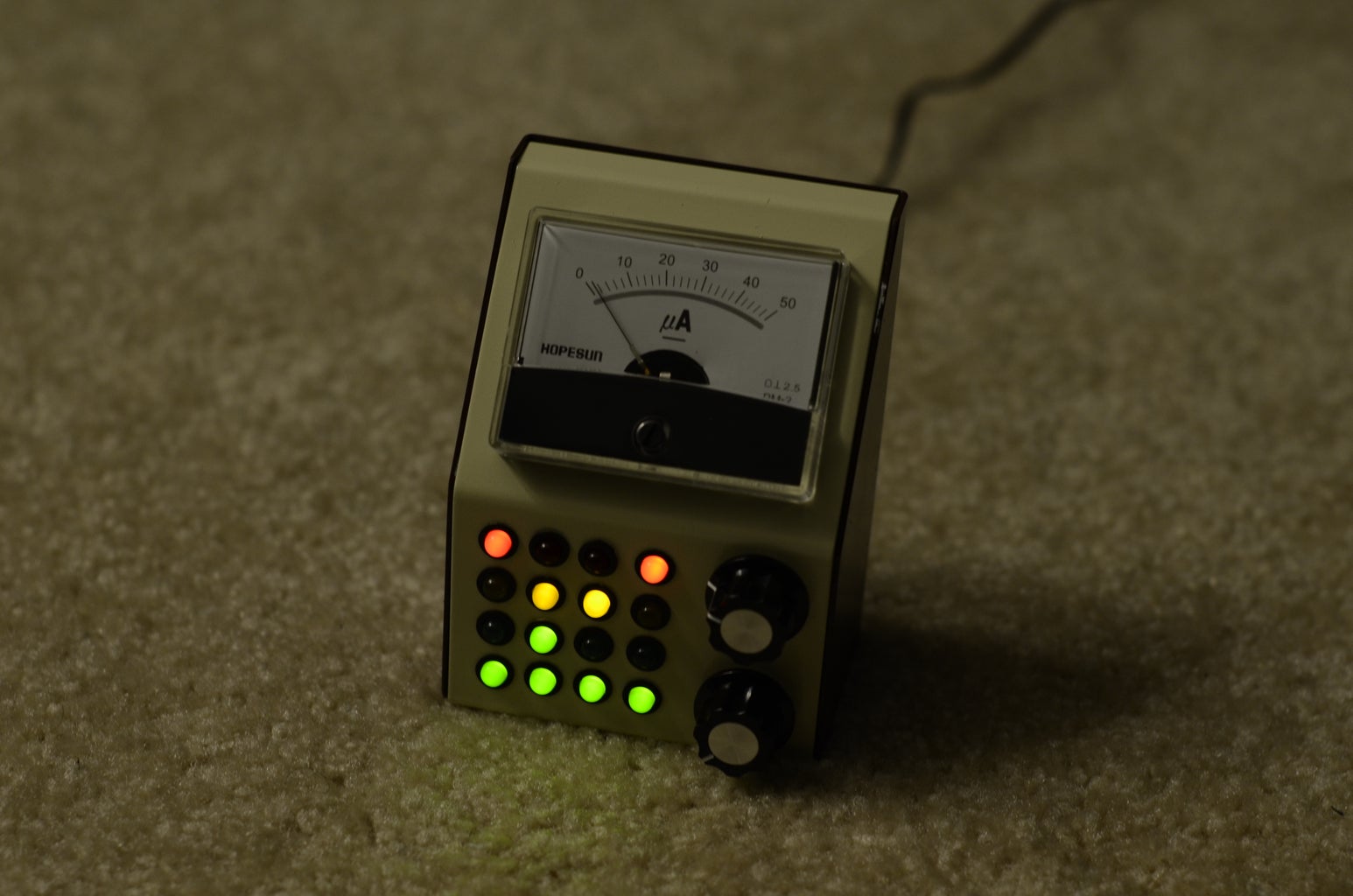
This is a guide to building an Arduino-powered clock that uses LEDs to display a 24-hour clock (hours and minutes) as binary digits, an analog meter to display the seconds, a switch to toggle between time-display and time-setting mode, and 2 knobs for setting the hours and minutes. This was designed from scratch, but is an improvement over other Arduino binary clocks that miss milliseconds here and there. This clock is extremely accurate and can be used and trusted.
To clear things up right away, Cwik is my last name and it's pronounced "Swick". So no, it's not the Quick Clock, and no, it does not run quick.
We'll start by using the Arduino Uno for prototyping, then build our own Arduino circuit from scratch for the final product. While creating our own circuit from scratch at the end is completely optional, it will allow you to continue to use your Cwik Clock, while freeing up the Uno for your next project.
Goals
There are 3 main goals for this project:
1) Familiarizing yourself with basic circuitry components - My Dad inspired me to get into electronics and circuits. After fixing some old oscilloscope by determining a resistor had blown, I was amazed that he could actually fix something (rather than throw it out and replace it). I have very little experience with circuits, but am determined to be able to hold a conversation with my dad that involves more than batteries, buzzers and light bulbs. By the end of this guide, you should gain knowledge of LEDs (safely powering them, and controlling using the Arduino), understand potentiometers (what they are, and reading their values from the arduino board), how an analog ammeter works, and using Ohm's Law.
2) Striving for functional perfection - Go big or go home. We're building this to high standards, a clock you can actually use and trust.
3) Making this look damn good - Although most of the concepts are simple, it doesn't mean our product has to look it too. Some key themes in its appearance are compactness, retro styling, throwbacks to audio equipment, fit & finish, and feel. My Dad had a lot of electronic equipement laying around the basement, so some colors and elements are inspired by my vague memories. Using an analog meter on a digital clock and a potentiometer to set digital time seems backwards, but it's what builds the charm of the Cwik Clock and differentiates itself from the countless binary clocks on the market already.
Audience
This guide is ideal for anyone looking for their 1st start-to-finish Arduino project. Elementary knowledge of the arduino platform, circuitry, and programming would be helpful, but aren't absolutely essential.
Step 1: Materials Needed

This guide leads you through creating a prototype, and finally creating the finished product. As such, the materials needed are split into 2 secions as well.
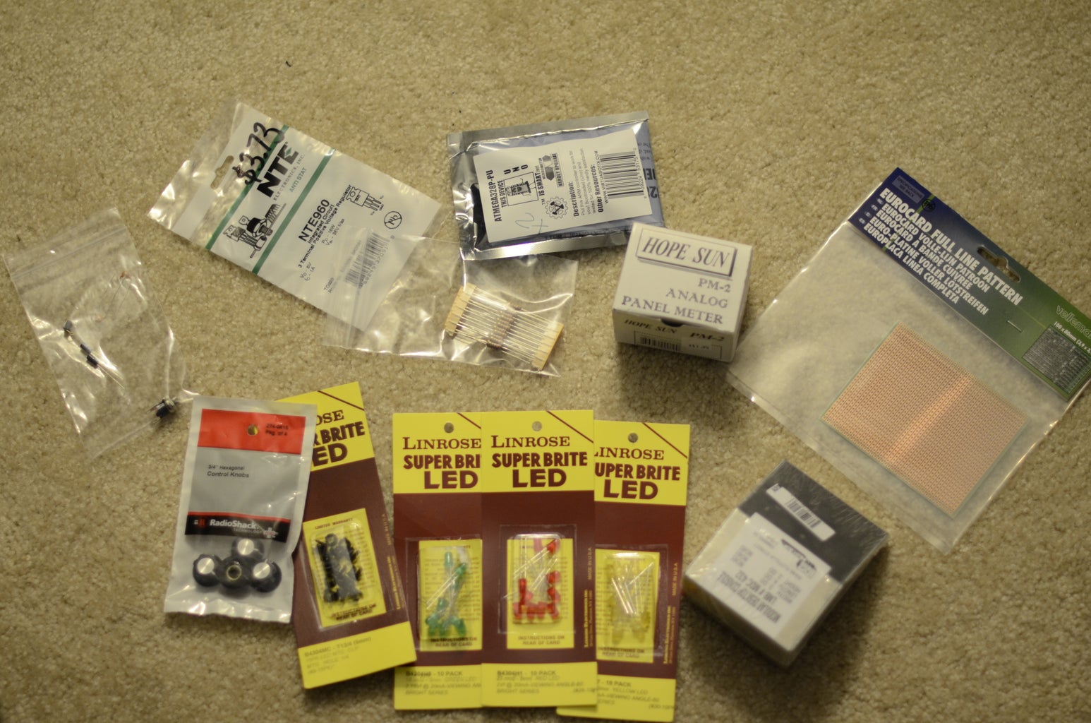
The Arduino Uno Based Circuit (used for the majority of the steps):
-1 x Arduino Uno
-14 x LEDs, 2Vf @ 20mA
-14 x 220 Ohm resistors
-2 x potentiometers (preferrably linear and can really be any resistance, but 10K or 100K Ohm will do well)
-1 x SPDT switch
-1 x 50 uA analog meter/ammeter
-1 x 100K Ohm resistor
The Final Circuit (re-uses everything from the above list, but now we're making an Arduino board rather than using the Uno):
-1 x ATmega328P-PU (or pull the one off of your Uno, but you'll want to replace it with this)
-1 x project box, paint if desired
-wire (I used 22 AWG wire)
-1 x 7805 voltage regulator (5V)
-1 x 10K Ohm resistor
-2 x 10 uF capacitor
-2 x 22 pF capacitor
-1 x 16 MHz clock crystal
-1 x momentary normally open ("off") button/switch
-2 x knobs, which fit on the potentiometers
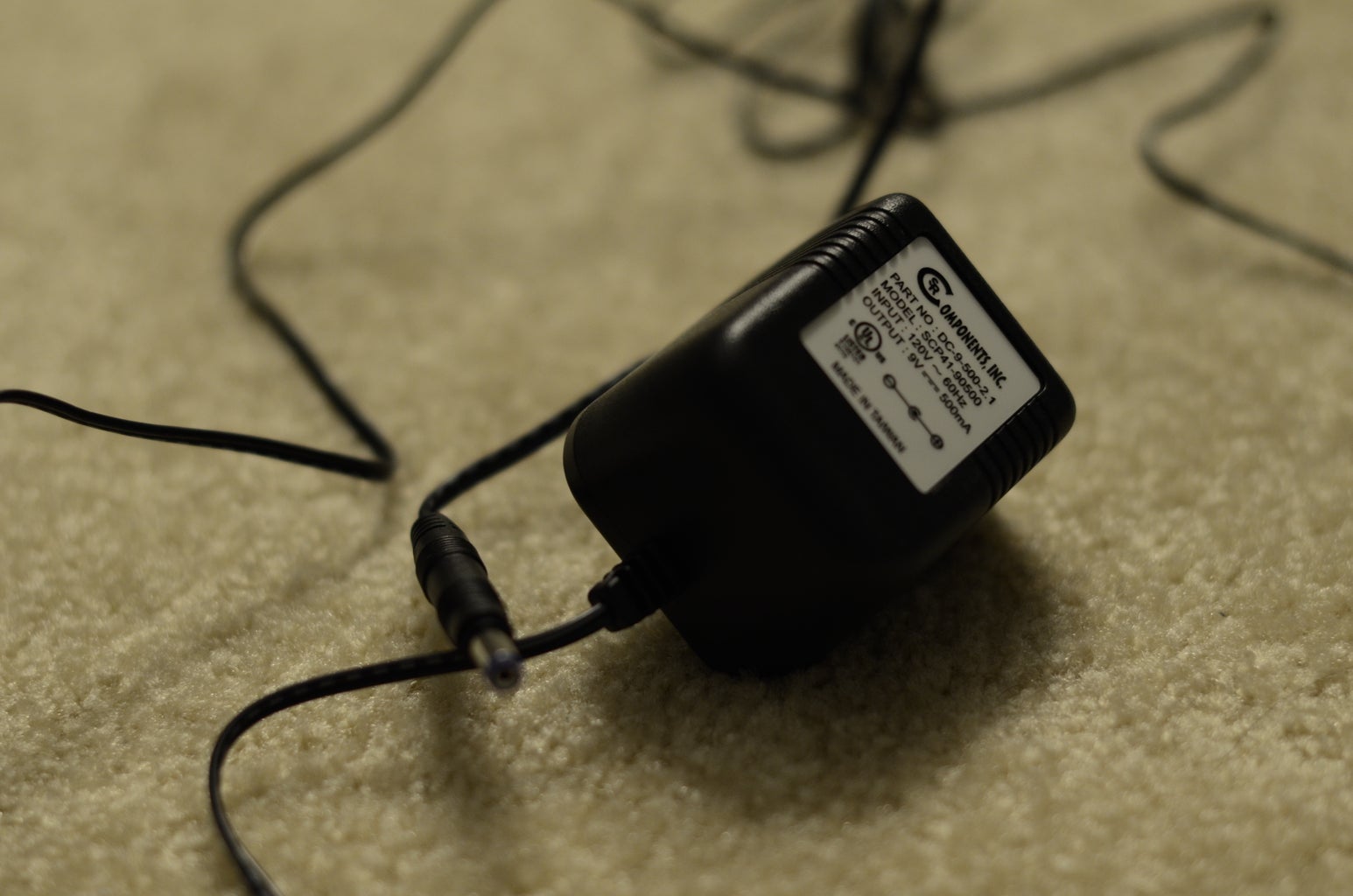
-1 x 9V power supply
-1 x female jack for power supply
-perf board
-2 x LED (optional, these are completely unused, but form a 4x4 grid of LEDs along with 13 time LEDs, and the 1 time-setting mode LED)
-14 x LED mounting clip (or 16 if you use the 2 dummy LEDs mentioned directly above, but these mounting clips are completely optional)
-1 x 28-pin socket for mounting the microcontroller (optional, but highly recommended if you plan to adjust for error in the final step)
Step 2: Reading the Clock


Each column of LEDs represents a single digit in a 24 hour clock in binary. If you don't undestand binary you may want to quickly read up on it.
In order to read the clock, the rows (starting from the bottom up) represent the numbers 1, 2, 4, and 8. To read the column, simply add the values that are lit up for the column.
Step 3: Powering the LEDs

Now that we know how to tell time with LEDs, it's time to figure out how to light up the LEDs.
The digital pins on the Arduino Uno output 5V DC. I purchased 2Vf @ 20mA LEDs, so the following calculations pertain to these values. Let's calculate what type of resistors will be needed in series to power our LEDs using Ohm's Law.
V = IR
R = V / I
R = ([voltage supplied by Arduino] - [voltage drop across LED]) / 20 mA
R = (5V - 2V) / 0.02 A
R = 150 Ω
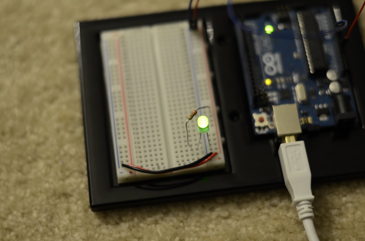
This means the resistor should be 150Ω. However, it's fairly common to use 220Ω resistors, and some people use even higher. The higher the resistance, the lower the intensity of the LED, but the higher the power saving (but at some point, the resistance it too high and there's not enough voltage to power the LED). Hence, to power a single LED, we need to hook it up in series with a 150Ω resistor (or 220 to be safe), apply 5V to the anode, and attach its cathode to ground.
In the diagram you can see the Arduino Uno powering a single LED. No program needs to be loaded on the board since we're just connecting directly to the 5V pin.
In order to make the clock's display, we'll require 13 LEDs (as shown in the previous step), each connected to their own 220Ω resistor. Rather than power the LEDs from the 5V pin, we'll be hooking them up to the digital pins of the Uno in the next step (so that we can turn them on and off when we want).
Step 4: Programming the Clock

In this step, we'll create a program to be uploaded onto the ATmega microcontroller on the Arduino Uno board. The program will power the 13 required LEDs to display a 24-hour clock in binary. In later steps, we'll worry about setting the time, but for now it will always start at 00:00.
Program Structure
Arduino programs have 2 main methods; a method that is run once at the beginning where initialization is done (called setup), and another method which is called continuously (called loop).
In setup(), we'll set the time to 00:00, and set up which pins are going to drive the 13 LEDs.
In loop() we'll see if more than a second has ellapsed (and if so, increment the time), then display the time by powering the proper LEDs. The millis() method is instrumental to keeping time. It returns the number of milliseconds that have ellapsed since the circuit was powered as an unsigned long. "Unsigned" means that it will not be negative, and long refers to how many bits (32 to be exact) are used to keep track of this number (bits are the number of binary digits).
The Quirk with millis()
Since there is a finite number of bits in an unsigned long, at some point we're going run out of digits! According to the Arduino documentation on millis(), it will wrap around (ie, reset back to zero) after approximately 50 days. How annoying would that be to have to reset your clock every 50 days? As one of the goals states, we're striving for functional perfection and this distruptive behavior is unnacceptable. Thus, the logic in our tick() method is used to see when we wrap around and continue without anyone being the wiser.
Pin Assignments
Before we jump right in and start assigning digital pins, we'll required a PWM (pulse width modulated) pin to display the seconds on the analog meter in a later step. On the Arduino Uno, pins 3, 5, 6, 9, 10, and 11 are enabled for PWM (as signified by the "~"). Thus, I'm saving pin 11 for the analog display, and using pins 0 - 10, 12 & 13 for the binary LED display.
The code
/*
Cwik Clock v1.0 - Prototyping the Display
Author: Dennis Cwik
Date: July 23, 2012
This program is the controller for a binary clock, with LEDs
attached to digital pins 0 through 10, 12, and 13.
This example code is in the public domain.
*/
// This can be modified for debug purposes to make a minute go by quicker.
int ONE_SECOND = 1000; // measured in milliseconds
int DELAY_BETWEEN_LOOP_CALLS = 200; // measured in milliseconds
// I didn't come up with this, it's from the arduino documentation
unsigned long MAX_UNSIGNED_LONG = 4294967295; // = (2 ^ 32) - 1
// 1st column of LEDs
int PIN_MIN1 = 0;
int PIN_MIN2 = 1;
int PIN_MIN4 = 2;
int PIN_MIN8 = 3;
// 2nd column of LEDs
int PIN_MIN10 = 4;
int PIN_MIN20 = 5;
int PIN_MIN40 = 6;
// 3rd column of LEDs
int PIN_HOUR1 = 7;
int PIN_HOUR2 = 8;
int PIN_HOUR4 = 9;
int PIN_HOUR8 = 10;
// 4th column of LEDs
int PIN_HOUR10 = 12;
int PIN_HOUR20 = 13;
// the last time the seconds in the time were incremented
unsigned long m_lastTick;
// used to tell us if we're setting the time or not
boolean m_inTimeSetMode = false;
// the time
byte m_second;
byte m_minute;
byte m_hour;
// the setup routine runs once when you press reset
void setup()
{
// initialize the pins used for outputting time as OUTPUT
pinMode(PIN_MIN1, OUTPUT);
pinMode(PIN_MIN2, OUTPUT);
pinMode(PIN_MIN4, OUTPUT);
pinMode(PIN_MIN8, OUTPUT);
pinMode(PIN_MIN10, OUTPUT);
pinMode(PIN_MIN20, OUTPUT);
pinMode(PIN_MIN40, OUTPUT);
pinMode(PIN_HOUR1, OUTPUT);
pinMode(PIN_HOUR2, OUTPUT);
pinMode(PIN_HOUR4, OUTPUT);
pinMode(PIN_HOUR8, OUTPUT);
pinMode(PIN_HOUR10, OUTPUT);
pinMode(PIN_HOUR20, OUTPUT);
// initialize clock variables
m_lastTick = 0;
setTime(0, 0, 0);
}
// the loop routine runs over and over again forever
void loop()
{
// see if we're setting the time, or letting time flow normally
if (m_inTimeSetMode)
{
getTimeFromPots();
}
else
{
tick();
}
// now that the time has been updated, show the time
displaySeconds();
displayMinutes();
displayHours();
// arbitrary delay so that we're not processing away 100% of the time,
// an act of power saving
delay(DELAY_BETWEEN_LOOP_CALLS);
}
/**
* A helper method to set m_second, m_minute, and m_hour.
*/
void setTime(byte newHour, byte newMinute, byte newSecond)
{
m_second = newSecond;
m_minute = newMinute;
m_hour = newHour;
}
/**
* This method keeps track of the logical flow of time. If enough time has
* passed since the last time it was called, m_second, m_minute, and m_hour
* will be updated appropriate. This takes into account that millis() rolls
* over roughly every 50 days.
*/
void tick()
{
unsigned long now = millis();
unsigned long msElapsed;
// first we need to find out how much time has passed since the last time we
// called tick()
if (now < m_lastTick)
{
// gasp, either we've succeeded in travelling back in time, or millis() wrapped around!
msElapsed = (MAX_UNSIGNED_LONG - m_lastTick) + now;
}
else
{
msElapsed = now - m_lastTick;
}
// for each second that has passed (hopefully just 1, unless our code is really laggy),
// add 1 second to the time, and increase the minutes & hours if necessary.
for (int i = 0; i < msElapsed / ONE_SECOND; ++i)
{
m_lastTick = m_lastTick + ONE_SECOND;
++m_second;
if (m_second == 60)
{
m_second = 0;
++m_minute;
if (m_minute == 60)
{
m_minute = 0;
++m_hour;
if (m_hour == 24)
{
m_hour = 0;
}
}
}
}
}
void displaySeconds()
{
// TODO control the analog display
}
/**
* This method reads the variable m_minute, converts it to binary, and displays
* it on the appropriate LEDs (those being PIN_MIN*).
*/
void displayMinutes()
{
byte ones = m_minute % 10;
digitalWrite(PIN_MIN1, ones & B1);
digitalWrite(PIN_MIN2, ones & B10);
digitalWrite(PIN_MIN4, ones & B100);
digitalWrite(PIN_MIN8, ones & B1000);
// division is kind of expensive, but we'll assume the compile optimizes this for us :)
byte tens = m_minute / 10;
digitalWrite(PIN_MIN10, tens & B1);
digitalWrite(PIN_MIN20, tens & B10);
digitalWrite(PIN_MIN40, tens & B100);
}
/**
* This method reads the variable m_hour, converts it to binary, and displays
* it on the appropriate LEDs (those being PIN_HOUR*).
*/
void displayHours()
{
byte ones = m_hour % 10;
digitalWrite(PIN_HOUR1, ones & B1);
digitalWrite(PIN_HOUR2, ones & B10);
digitalWrite(PIN_HOUR4, ones & B100);
digitalWrite(PIN_HOUR8, ones & B1000);
byte tens = m_hour / 10;
digitalWrite(PIN_HOUR10, tens & B1);
digitalWrite(PIN_HOUR20, tens & B10);
}
/**
* This method reads the values from the 2 potentiometers, converts them to
* mimnutes and hours, and sets m_minute and m_hour to the associated values.
*/
void getTimeFromPots()
{
// TODO read the potentiometers, set the hour and minutes
}
Step 5: Prototyping the Display

It's time to hook up the resistors and LEDs to the Arduino. Remember, when uploading your program to the Uno, pin 0 must be unused or you will get a very ambiguous error message. Since we use it in our circuit, unplug the lead, upload, then replug the lead.
You can see the clock in action in the following video. Please note, I've sped up the clock so that a minute passes in less than 1 second.
Step 6: Setting the Time With Potentiometers
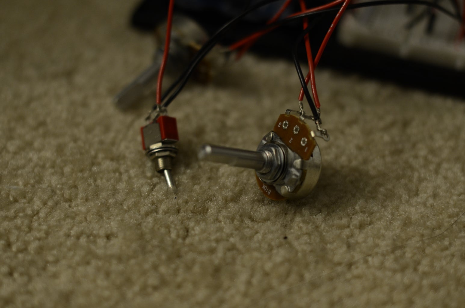

We will be using potentiometers to set the time. The potentiometers will be used as variable resistors; the more you turn the knob, the more resistance the unit has.
If you're curious, a potientiometer works as a voltage divider. The reason why the resistance of the potentiometer is not necessary is because it's the only load between 5V and ground. Thus, on one extreme end of the knob you're connected directly to ground (0V), on the other extreme you're connected directly to 5V, and in between you'll get a smooth transistion from 0 to 5V. If you added some other load in series to one of the outside pins, then you'd need to carefully consider what resistance the potentiometer should be.
Reading Values from Potentiometers
In order to set time using potentiometers, we'll hook up one outside lead to ground and the other outside lead to 5V, and measure the voltage from the middle lead using analogRead(). This will return a value between 0 (0V) and 1023 (5V). After that, it's just a matter of scaling the value to the number of hours (24) and minutes (60). We'll read the hours from pin A0, and the minutes from pin A1.
Behavior of Potentiometers (ie, Taper)
The relationship between the angle of the knob and the amount of resistance is known as the taper. Volume knobs often have a non-linear taper, where it requires more of a turn near the end to make a difference. Since all hour and minute values are equal, it seems logical to have a linear taper.
The Code
All that's needed is to set the m_inTimeSetMode to true for this step, and add the implementation for the getTimeFromPots() method to test out our time setting:
boolean m_inTimeSetMode = true;
int HOUR_INPUT_PIN = A0;
int MIN_INPUT_PIN = A1;
/**
* This method reads the values from the 2 potentiometers, converts them to
* minutes and hours, and sets m_minute and m_hour to the associated values.
*/
void getTimeFromPots()
{
// read the potentiometers
int hourSensor = analogRead(HOUR_INPUT_PIN);
int minuteSensor = analogRead(MIN_INPUT_PIN);
// scale the readings (from 0 to 1023) to the appropriate scale (0 to 23 for hours, 0 to 59 for minutes)
setTime(map(hourSensor, 0, 1023, 0, 23), map(minuteSensor, 0, 1023, 0, 59), 0);
// we set the last tick to now, because when we set m_inTimeSetMode to false,
// many seconds could have passed since the last one, and the time would jump ahead
m_lastTick = millis();
}
Step 7: Prototyping the Display and Time Setting

Our program is useless if m_inTimeSetMode is only ever set at the beginning of the program, so let's work on being able to set this variable using a switch.
For this, we'll use a single pole double throw (SPDT) switch, or an "on - on" switch. Attach the middle lead to analog input A2, one of the outside leads to ground, and the other outside lead to 5V. The analogRead(A2) method should now return 0 or 1023 when the switch is toggled back and forth.
We'll want to visually tell the user they're in time setting mode with an LED. The Uno only has 14 digital pins, and since we're already using all of them (13 for the time LEDs, and 1 pin for the PWM that will be used on the analog meter), we can luckily turn an analog pin into a digital out pin! Simply call pinMode(A5, OUTPUT) to use A5 as a digital output pin.
We'll need to check if we're in time-setting or time-displaying mode at the very beginning of the loop() method. We'll put that logic in a method called checkMode().
Now you have a binary clock that keeps time, and can be set manually by the user!
The Entire Code So Far
/*
Cwik Clock v1.0 - Prototyping the Display
Author: Dennis Cwik
Date: July 23, 2012
This program is the controller for a binary clock, with LEDs
attached to digital pins 0 through 10, 12, and 13, allows for time
setting with potentiometers, and can be toggled between time
setting mode and time display mode.
This example code is in the public domain.
*/
// This can be modified for debug purposes to make a minute go by quicker.
int ONE_SECOND = 1000; // measured in milliseconds
int DELAY_BETWEEN_LOOP_CALLS = 200; // measured in milliseconds
// I didn't come up with this, it's from the arduino documentation
unsigned long MAX_UNSIGNED_LONG = 4294967295; // = (2 ^ 32) - 1
int HOUR_INPUT_PIN = A0;
int MIN_INPUT_PIN = A1;
int CLOCK_MODE_SWITCH_PIN = A2;
int CLOCK_MODE_LED_PIN = A5;
// 1st column of LEDs
int PIN_MIN1 = 0;
int PIN_MIN2 = 1;
int PIN_MIN4 = 2;
int PIN_MIN8 = 3;
// 2nd column of LEDs
int PIN_MIN10 = 4;
int PIN_MIN20 = 5;
int PIN_MIN40 = 6;
// 3rd column of LEDs
int PIN_HOUR1 = 7;
int PIN_HOUR2 = 8;
int PIN_HOUR4 = 9;
int PIN_HOUR8 = 10;
// 4th column of LEDs
int PIN_HOUR10 = 12;
int PIN_HOUR20 = 13;
// the last time the seconds in the time were incremented
unsigned long m_lastTick;
// used to tell us if we're setting the time or not
boolean m_inTimeSetMode = false;
// the time
byte m_second;
byte m_minute;
byte m_hour;
// the setup routine runs once when you press reset:
void setup()
{
// using one of the analog inputs as output
pinMode(CLOCK_MODE_LED_PIN, OUTPUT);
// initialize the pins used for outputting time as OUTPUT
pinMode(PIN_MIN1, OUTPUT);
pinMode(PIN_MIN2, OUTPUT);
pinMode(PIN_MIN4, OUTPUT);
pinMode(PIN_MIN8, OUTPUT);
pinMode(PIN_MIN10, OUTPUT);
pinMode(PIN_MIN20, OUTPUT);
pinMode(PIN_MIN40, OUTPUT);
pinMode(PIN_HOUR1, OUTPUT);
pinMode(PIN_HOUR2, OUTPUT);
pinMode(PIN_HOUR4, OUTPUT);
pinMode(PIN_HOUR8, OUTPUT);
pinMode(PIN_HOUR10, OUTPUT);
pinMode(PIN_HOUR20, OUTPUT);
// initialize clock variables
m_lastTick = 0;
setTime(2, 18, 0);
}
// the loop routine runs over and over again forever:
void loop()
{
checkMode();
// see if we're setting the time, or letting time flow normally
if (m_inTimeSetMode)
{
getTimeFromPots();
}
else
{
tick();
}
// now that the time has been updated, show the time
displaySeconds();
displayMinutes();
displayHours();
// arbitrary delay so that we're not processing away 100% of the time,
// an act of power saving
delay(DELAY_BETWEEN_LOOP_CALLS);
}
/**
* A helper method to set m_hour, m_minute, and m_second.
*/
void setTime(byte newHour, byte newMinute, byte newSecond)
{
m_second = newSecond;
m_minute = newMinute;
m_hour = newHour;
}
/**
* This method keeps track of the logical flow of time. If enough time has
* passed since the last time it was called, m_second, m_minute, and m_hour
* will be updated appropriate. This takes into account that millis() rolls
* over roughly every 50 days.
*/
void tick()
{
unsigned long now = millis();
unsigned long msElapsed;
// first we need to find out how much time has passed since the last time we
// called tick()
if (now < m_lastTick)
{
// gasp, either we've succeeded in travelling back in time, or millis() wrapped around!
msElapsed = (MAX_UNSIGNED_LONG - m_lastTick) + now;
}
else
{
msElapsed = now - m_lastTick;
}
// for each second that has passed (hopefully just 1, unless our code is really laggy),
// add 1 second to the time, and increase the minutes & hours if necessary.
for (int i = 0; i < msElapsed / ONE_SECOND; ++i)
{
m_lastTick = m_lastTick + ONE_SECOND;
++m_second;
if (m_second == 60)
{
m_second = 0;
++m_minute;
if (m_minute == 60)
{
m_minute = 0;
++m_hour;
if (m_hour == 24)
{
m_hour = 0;
}
}
}
}
}
void displaySeconds()
{
// TODO control the analog display
}
/**
* This method reads the variable m_minute, converts it to binary, and displays
* it on the appropriate LEDs (those being PIN_MIN*).
*/
void displayMinutes()
{
byte ones = m_minute % 10;
digitalWrite(PIN_MIN1, ones & B1);
digitalWrite(PIN_MIN2, ones & B10);
digitalWrite(PIN_MIN4, ones & B100);
digitalWrite(PIN_MIN8, ones & B1000);
// division is kind of expensive, but we'll assume the compile optimizes this for us :)
byte tens = m_minute / 10;
digitalWrite(PIN_MIN10, tens & B1);
digitalWrite(PIN_MIN20, tens & B10);
digitalWrite(PIN_MIN40, tens & B100);
}
/**
* This method reads the variable m_hour, converts it to binary, and displays
* it on the appropriate LEDs (those being PIN_HOUR*).
*/
void displayHours()
{
byte ones = m_hour % 10;
digitalWrite(PIN_HOUR1, ones & B1);
digitalWrite(PIN_HOUR2, ones & B10);
digitalWrite(PIN_HOUR4, ones & B100);
digitalWrite(PIN_HOUR8, ones & B1000);
byte tens = m_hour / 10;
digitalWrite(PIN_HOUR10, tens & B1);
digitalWrite(PIN_HOUR20, tens & B10);
}
/**
* This method reads the values from the 2 potentiometers, converts them to
* mimnutes and hours, and sets m_minute and m_hour to the associated values.
*/
void getTimeFromPots()
{
// read the potentiometers
int hourSensor = analogRead(HOUR_INPUT_PIN);
int minuteSensor = analogRead(MIN_INPUT_PIN);
// scale the readings (from 0 to 1023) to the appropriate scale (0 to 23 for hours, 0 to 59 for minutes)
setTime(map(hourSensor, 0, 1023, 0, 23), map(minuteSensor, 0, 1023, 0, 59), 0);
// we set the last tick to now, because when we set m_inTimeSetMode to false,
// many seconds could have passed since the last one, and the time would jump ahead
m_lastTick = millis();
}
/**
* This method checks CLOCK_MODE_SWITCH_PIN to see if it's HIGH. If it is,
* it means we're now in clock set mode (m_inTimeSetMode is set to true), and
* turns the CLOCK_MODE_LED_PIN on.
*/
void checkMode()
{
m_inTimeSetMode = (analogRead(CLOCK_MODE_SWITCH_PIN) > 512);
digitalWrite(CLOCK_MODE_LED_PIN, m_inTimeSetMode);
}
Step 8: Displaying Seconds in an Analog Meter
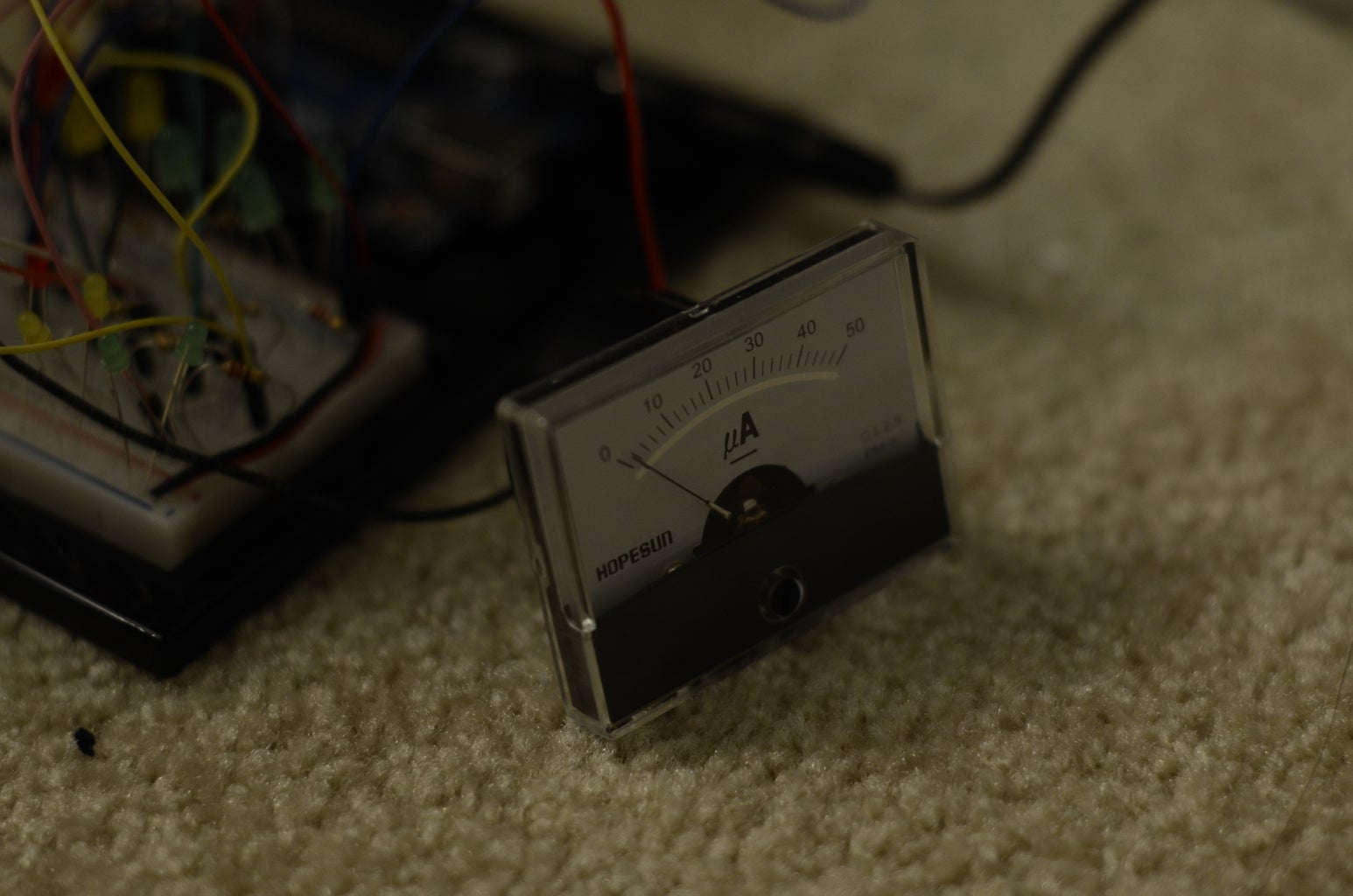
When looking for an analog meter, you'll most likely find ammeters (ones that measure current) and voltmeters (ones that measure voltage). I opted to use an ammeter.
An ammeter is a meter that is hooked up in series with the circuit, and thoeretically has 0 resistance (and a voltmeter is hooked up in parallel and theoretically has infinite resistance). What's important when buying your ammeter is the maximum current it measures. In order to swing the needle to 100%, your circuit must draw that much current. 1 A (or Amp) of current is enough to cause serious injury (I've been told it's enough to stop your heart). Aside from it being dangerous, our circuit probably won't be able to generate that much current. According to this article, most microcontrollers can output about 5mA of current, some less, so you should buy an ammeter whose full value (100%) is less than 5mA.
I purchased a 50uA ammeter. If I were to feed 5V (which is what the Arduino digital pins supply) into this ammeter without a current-limiting resistor, I'd probably see the needle swing to (or past) 100% and most likely damage the meter. In order to figure what resistance is needed, we turn back to Ohm's Law.
V = IR
R = V / I
R = 5V / 50uA
R = 5V / 0.000050 A
R = 100KΩ
So, connecting a 100KΩ resistor in series to the ammeter and applying 5V to the circuit would cause the needle to stay safely at 100%.
Getting the meter to display a fraction of 100% is done simply by using PWM (pulse width modulation). You can read up on it, but by applying 5V and 0V alternating at a specifc ratio, you can effectively get the needle to stay at any position between 0 and 100%. Due to how the meter is constructed, the needle's movement is natually dampened and you won't see any pulsing or jittering of the needle!
Step 9: Prototyping the Display, Time Setting, and Seconds
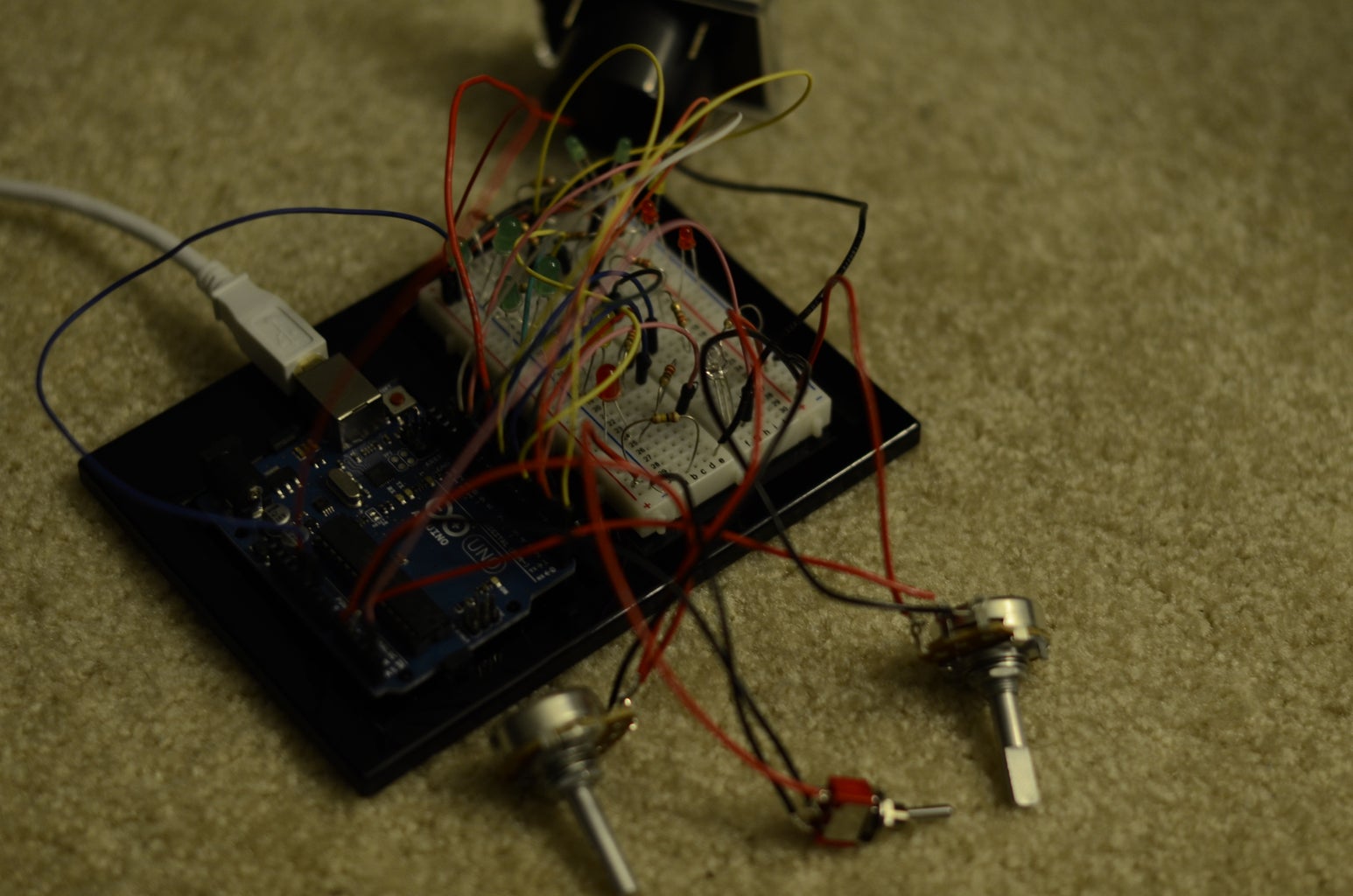


Now that we have the base program for running a binary clock, the know-how to read from potentiometers, and are experts in using ammeters, it's time to put it all together! It may look like a rat's nest of cables and components, but you shouldn't have any issues if you follow along step-by-step.
In the following video, I use the reset switch on the Uno to start our program from the beginning (time 00:00). You can see the seconds counting on the analog meter which unfortunately has a max value of 50, not 60 (but we can open it up and swap out the background if desired). Regardless of what the meter reads, it "ticks" 60 times per minute. After a full minute, we see the time change to 00:01, and the analog meter resets. I later switch into time setting mode (this is when the orange LED at the top center turns on), at which point you can see the seconds reset to 0. I set the time to 16:59, and the moment I turn time setting mode off (the orange LED at the top center turns off), the seconds on the analog meter start to count up again. I then wait another minute, at which point the time changes to 17:00.
The Final Code
/*
Cwik Clock v1.0 - Prototyping the Display
Author: Dennis Cwik
Date: July 23, 2012
This program is the controller for a binary clock, with LEDs
attached to digital pins 0 through 10, 12, and 13. 2 potentiometers
connected to A0 and A1 control the hours and minutes respectively,
and only when A2 is pulled high. When A2 is pulled high, an LED on
pin A5 will light up to tell the user that they are in time set mode.
Finally, pin 11 is used with PWM to show the seconds on an analog
ammeter.
This example code is in the public domain.
*/
// This can be modified for debug purposes to make a minute go by quicker.
int ONE_SECOND = 1000; // measured in milliseconds
int DELAY_BETWEEN_LOOP_CALLS = 200; // measured in milliseconds
// I didn't come up with this, it's from the arduino documentation
unsigned long MAX_UNSIGNED_LONG = 4294967295; // = (2 ^ 32) - 1
int HOUR_INPUT_PIN = A0;
int MIN_INPUT_PIN = A1;
int CLOCK_MODE_SWITCH_PIN = A2;
int CLOCK_MODE_LED_PIN = A5;
// 1st column of LEDs
int PIN_MIN1 = 0;
int PIN_MIN2 = 1;
int PIN_MIN4 = 2;
int PIN_MIN8 = 3;
// 2nd column of LEDs
int PIN_MIN10 = 4;
int PIN_MIN20 = 5;
int PIN_MIN40 = 6;
// 3rd column of LEDs
int PIN_HOUR1 = 7;
int PIN_HOUR2 = 8;
int PIN_HOUR4 = 9;
int PIN_HOUR8 = 10;
// PWM on the analog meter to display seconds.
int SEC_OUTPUT_PIN = 11;
// 4th column of LEDs
int PIN_HOUR10 = 12;
int PIN_HOUR20 = 13;
// the last time the seconds in the time were incremented
unsigned long m_lastTick;
// used to tell us if we're setting the time or not
boolean m_inTimeSetMode = false;
// the time
byte m_second;
byte m_minute;
byte m_hour;
/**
* Mandatory setup routine for Arduino, is run once at the very beginning.
*/
void setup()
{
// using one of the analog inputs as output
pinMode(CLOCK_MODE_LED_PIN, OUTPUT);
// initialize the pins used for outputting time
pinMode(PIN_MIN1, OUTPUT);
pinMode(PIN_MIN2, OUTPUT);
pinMode(PIN_MIN4, OUTPUT);
pinMode(PIN_MIN8, OUTPUT);
pinMode(PIN_MIN10, OUTPUT);
pinMode(PIN_MIN20, OUTPUT);
pinMode(PIN_MIN40, OUTPUT);
pinMode(PIN_HOUR1, OUTPUT);
pinMode(PIN_HOUR2, OUTPUT);
pinMode(PIN_HOUR4, OUTPUT);
pinMode(PIN_HOUR8, OUTPUT);
pinMode(PIN_HOUR10, OUTPUT);
pinMode(PIN_HOUR20, OUTPUT);
// initialize clock variables
m_lastTick = 0;
setTime(0, 0, 0);
}
/**
* Mandatory method for Arduino, it's called continuously after setup().
*/
void loop()
{
checkMode();
// see if we're setting the time, or letting time flow normally
if (m_inTimeSetMode)
{
getTimeFromPots();
}
else
{
tick();
}
// now that the time has been updated, show the time
displaySeconds();
displayMinutes();
displayHours();
// arbitrary delay so that we're not processing away 100% of the time,
// an act of power saving
delay(DELAY_BETWEEN_LOOP_CALLS);
}
/**
* A helper method to set m_hour, m_minute, and m_second.
*/
void setTime(byte newHour, byte newMinute, byte newSecond)
{
m_second = newSecond;
m_minute = newMinute;
m_hour = newHour;
}
/**
* This method keeps track of the logical flow of time. If enough time has
* passed since the last time it was called, m_second, m_minute, and m_hour
* will be updated appropriate. This takes into account that millis() rolls
* over roughly every 50 days.
*/
void tick()
{
unsigned long now = millis();
unsigned long msElapsed;
// first we need to find out how much time has passed since the last time we
// called tick()
if (now < m_lastTick)
{
// gasp, either we've succeeded in travelling back in time, or millis() wrapped around!
msElapsed = (MAX_UNSIGNED_LONG - m_lastTick) + now;
}
else
{
msElapsed = now - m_lastTick;
}
// for each second that has passed (hopefully just 1, unless our code is really laggy),
// add 1 second to the time, and increase the minutes & hours if necessary
for (int i = 0; i < msElapsed / ONE_SECOND; ++i)
{
m_lastTick = m_lastTick + ONE_SECOND;
++m_second;
if (m_second == 60)
{
m_second = 0;
++m_minute;
if (m_minute == 60)
{
m_minute = 0;
++m_hour;
if (m_hour == 24)
{
m_hour = 0;
}
}
}
}
}
/**
* This method uses PWM to display the m_second on an analog meter connected
* to SEC_OUTPUT_PIN.
*/
void displaySeconds()
{
analogWrite(SEC_OUTPUT_PIN, map(m_second, 0, 59, 0, 255));
}
/**
* This method reads the m_minute, converts it to binary, and displays
* it on the appropriate LEDs (those being PIN_MIN*).
*/
void displayMinutes()
{
byte ones = m_minute % 10;
digitalWrite(PIN_MIN1, ones & B1);
digitalWrite(PIN_MIN2, ones & B10);
digitalWrite(PIN_MIN4, ones & B100);
digitalWrite(PIN_MIN8, ones & B1000);
// division is kind of expensive, but we'll assume the compile optimizes this for us :)
byte tens = m_minute / 10;
digitalWrite(PIN_MIN10, tens & B1);
digitalWrite(PIN_MIN20, tens & B10);
digitalWrite(PIN_MIN40, tens & B100);
}
/**
* This method reads the m_hour, converts it to binary, and displays
* it on the appropriate LEDs (those being PIN_HOUR*).
*/
void displayHours()
{
byte ones = m_hour % 10;
digitalWrite(PIN_HOUR1, ones & B1);
digitalWrite(PIN_HOUR2, ones & B10);
digitalWrite(PIN_HOUR4, ones & B100);
digitalWrite(PIN_HOUR8, ones & B1000);
byte tens = m_hour / 10;
digitalWrite(PIN_HOUR10, tens & B1);
digitalWrite(PIN_HOUR20, tens & B10);
}
/**
* This method reads the values from the 2 potentiometers, converts them to
* mimnutes and hours, and sets m_minute and m_hour to the associated values.
*/
void getTimeFromPots()
{
// read the potentiometers
int hourSensor = analogRead(HOUR_INPUT_PIN);
int minuteSensor = analogRead(MIN_INPUT_PIN);
// scale the sensor readings (from 0 to 1023) to the appropriate
// scale (0 to 23 for hours, 0 to 59 for minutes)
setTime(map(hourSensor, 0, 1023, 0, 23), map(minuteSensor, 0, 1023, 0, 59), 0);
// we set the last tick to now, because when we set m_inTimeSetMode to false,
// many seconds could have passed since the last one, and the time would jump ahead
m_lastTick = millis();
}
/**
* This method checks CLOCK_MODE_SWITCH_PIN to see if it's HIGH. If it is,
* it means we're now in clock set mode (m_inTimeSetMode is set to true), and
* turns the CLOCK_MODE_LED_PIN on.
*/
void checkMode()
{
m_inTimeSetMode = (analogRead(CLOCK_MODE_SWITCH_PIN) > 512);
digitalWrite(CLOCK_MODE_LED_PIN, m_inTimeSetMode);
}
Step 10: Goodbye Prototype, Hello Production
While not necessary, creating a production circuit will free up your Uno for another project. Theoretically it means you'll also be able to create a smaller board, since you won't require a USB connection or other components that aren't used by the Cwik Clock! How small of a production board you can make boils down to your ability to solder in tight areas, and the way your PCB is constructed.
The Schematic
The schematic for the Arduino boards are available for you to download and use (please take a moment to thank the folks in Italy for making the hardware open source too!), but I've opted for a far lazier approach; using "Setting up an Arduino on a breadboard" guide written by Carlyn Maw and updated by Rory Nugent as my guide (please take a moment to thank Carlyn and Rory!). By following along until the end of step 3 (but using our program on the ATmega), you should be able to replicate the circuit made in the previous step without your Arduino Uno.
The Circuit
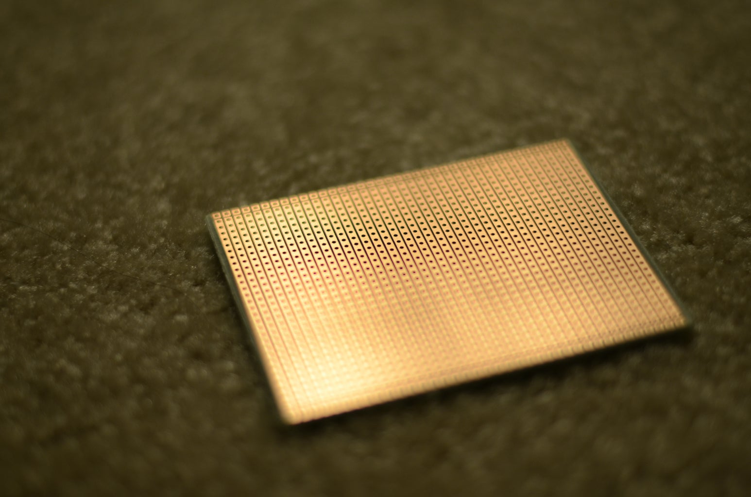
It's up to you to determine how to transform that circuit into something more permanent. I decided to go with a type of perfboard, using a knife to cut the copper lines when needed. Some other options are to etch your own circuit, or have a company print you your circuit.
Step 11: Finding an Enclosure
Enclosure Selection
Despite some awesome concepts in my head, I was limited to enclosures that were reasonably priced and easy to get my hands on. You could make your own enclosure, but one of my goals is to make the Cwik Clock look damn good, and my craftsman skills aren't that great.
In selecting your enclosure, you'll have to consider a few aspects:
1) You'll need to cut holes in the surface in order to have the LEDs poke through, and a sizeable hole is needed for the ammeter to sit in. A heavier material (like metal) may look nicer, but requires a bit more effort to cut through.
2) It has to be big enough to house the ATmega microcontroller, the potentiometers (which can be decently bulky), and the ammeter's large back, along with the rest of the capacitors, resistors, and loose wire. The smaller you make it, the nicer it will look, but the more effort is required to assemble.
3) How will the clock look sitting on a desk or a shelf? Will the LEDs be easily visible? As attractive as your analog meter may be, I'd argue that the minutes and hours are far more important to a user than what the seconds read. It should be easier to see the minutes and hours over the seconds. Remember, we're building a functional clock that will actually be used and trusted!
4) Where will the controls go? Most electronic equipment will put controls on the front of the unit, and sometimes the top. Rarely will you find controls and outputs on the sides of the device. In order to make the device look professional, I'd recommend trying to stick with not putting any controls on the sides. Regardless, you should ensure your potentiometer or time setting switch don't easily block the view of the LEDs or analog meter.
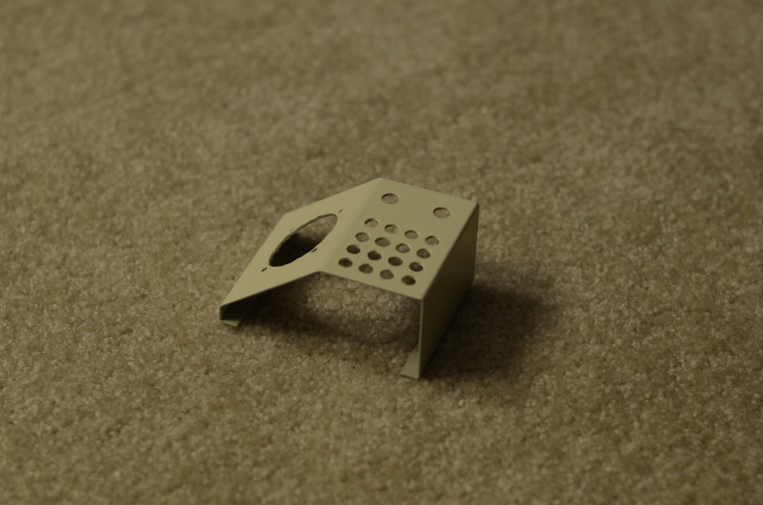
Cutting the Enclosure
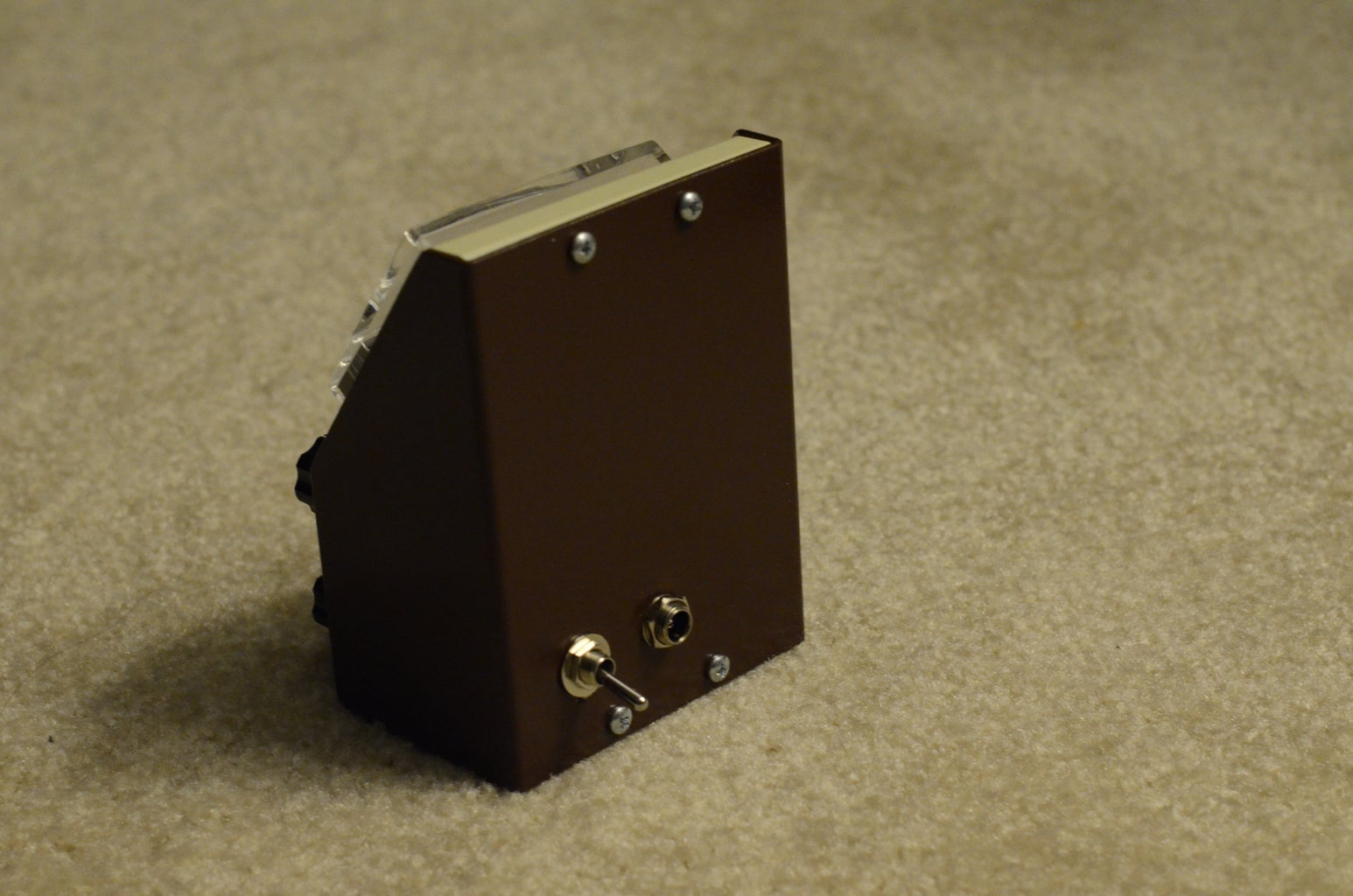
Most enclosures will have 2 separate peices, like the body and the top cover. Your placement of components may require you to place items of both peices. Either make sure that you can easily detatch components from one of the sides (recommended), or have a lot of slack wire. By doing this, debugging or maintenance will be much easier if you ever have to crack it open in the future. In my design, the only components on the back are the power input and time setting mode, both of which can be unscrewed.
After finding out the final position for the LEDs, the analog meter, the knobs, the time setting switch, and the power input, I covered my enclosure with masking tape so that I could easily draw/erase positions to cut. Using a drill and dremel, I was able to cut all necessary holes in my enclosure.
Painting the Enclosure
After sanding down any rough edges, it's ready for painting. I used the cheapest glossy spray paint I could find, in retro-tastic colors. Before painting, double check that all of your components fit in their holes, otherwise you may need to repaint.
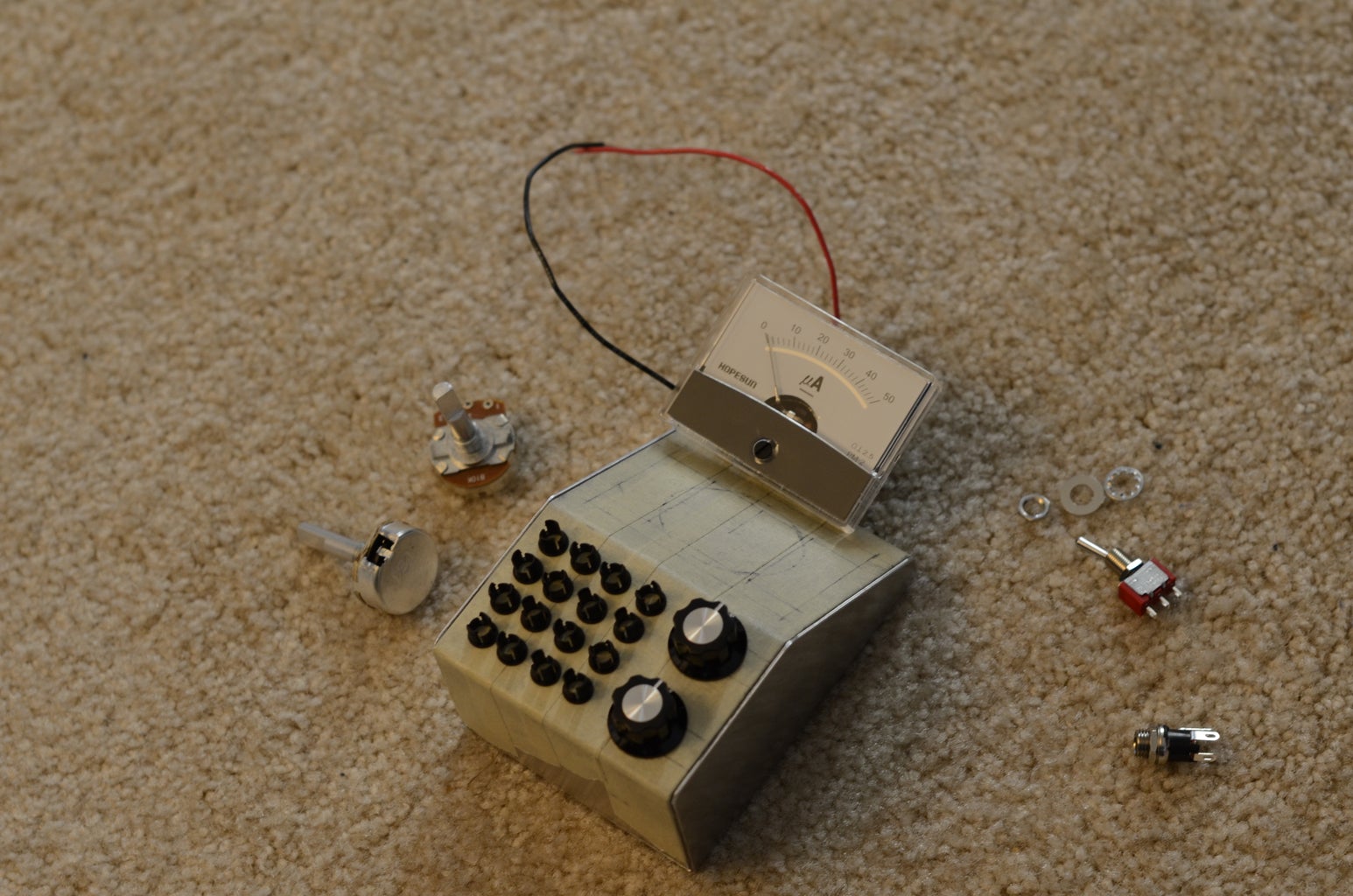
Step 12: Preparing the Components

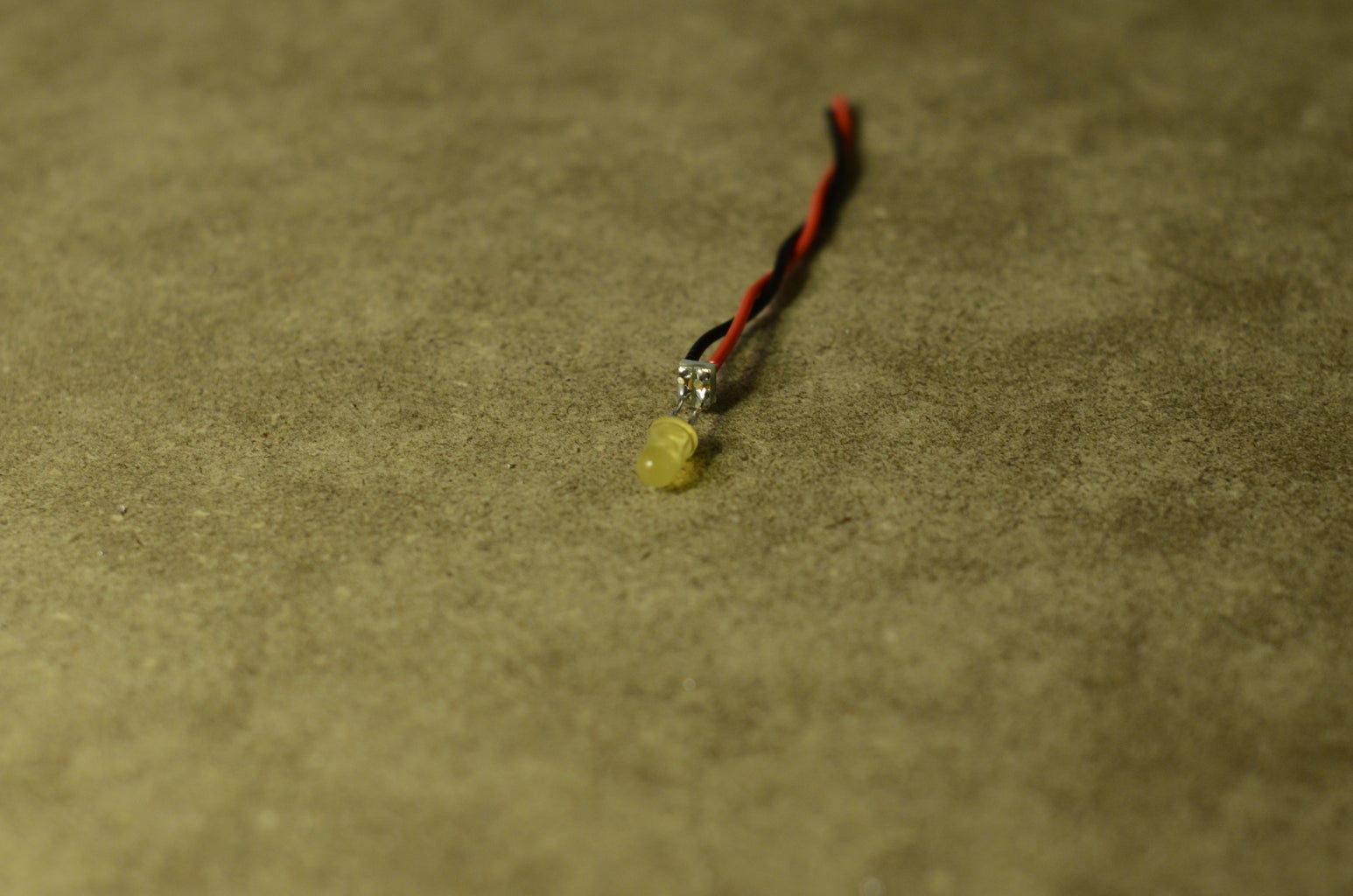


The LEDs
Rather than solder the LEDs directly to our circuit board and risk getting the heights of the LEDs wrong on the surface of the clock, I've opted to attach wires to the back. I did this by cutting 14 2x2 perforboard squares, so that the anodes and cathodes can be connected to wires easily.
The Potentiometers
I tried to trim the body and shaft of the potentiometers in an effort to save on space, but ended up killing them. Either I cut something that was was critical (which I don't think happened), or the unit got too hot while cutting and fried something. I wouldn't recommend modifying the potentiometers if at all possible!
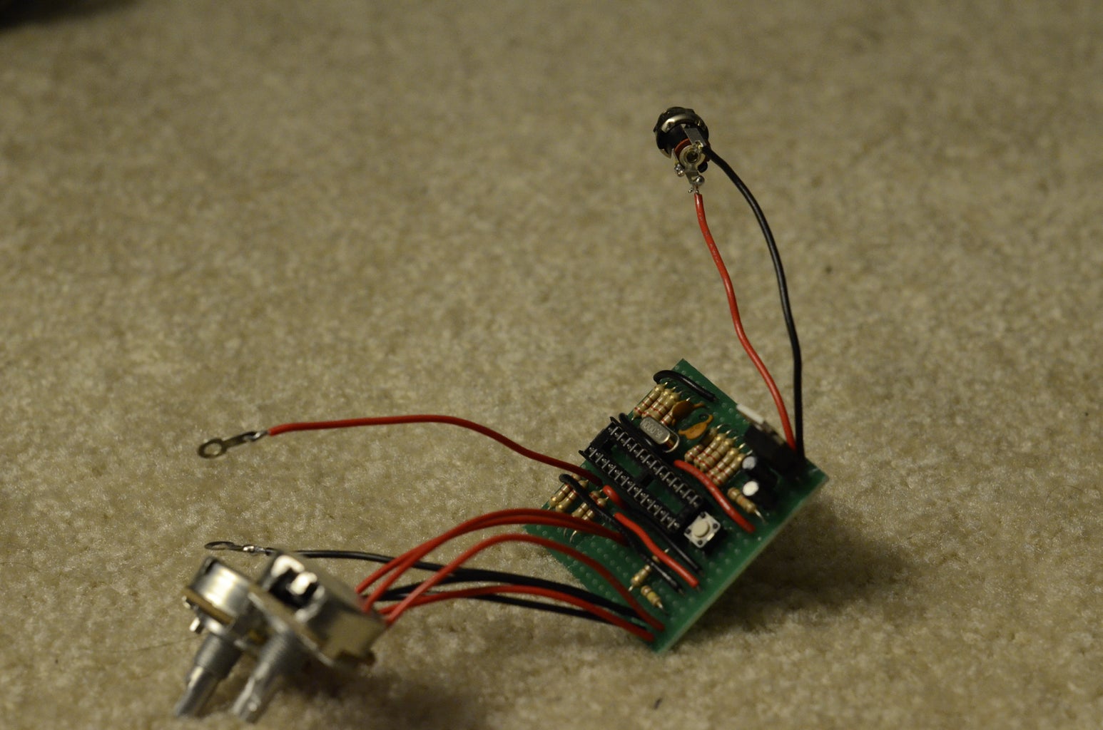
The Perf Board
You can easily score the traces with a sharp knife. I effectively cut a "V" shape into the top so that I'd actually be removing roughly 0.5mm of copper, rather than just cutting and hoping that the 2 sections don't short. Make sure the resistance between the sections you cut is incredibly high (ie, not shorted) just to be safe. See the images for the placement of all components on the perfboard, but before you start, make sure you know which pins on the ATmega go where since it will probably sit on the non-copper side! I made the mistake of cutting some traces before realizing the ATmega chip would sit on the other side of my perf board, meaning the pins would be mirrored. Luckily I was able to recover.
The SPDT switch and potentiometers need to have one end attached to the 5V rail, and the other end attached to the GND rail. Also, all LEDs (M1, M2, ... M20, M40, H1, H2, ... H10, H20, and time mode LED) will need the anode attached to the labels in the drawing, and the cathode attached to either of the GND rails.
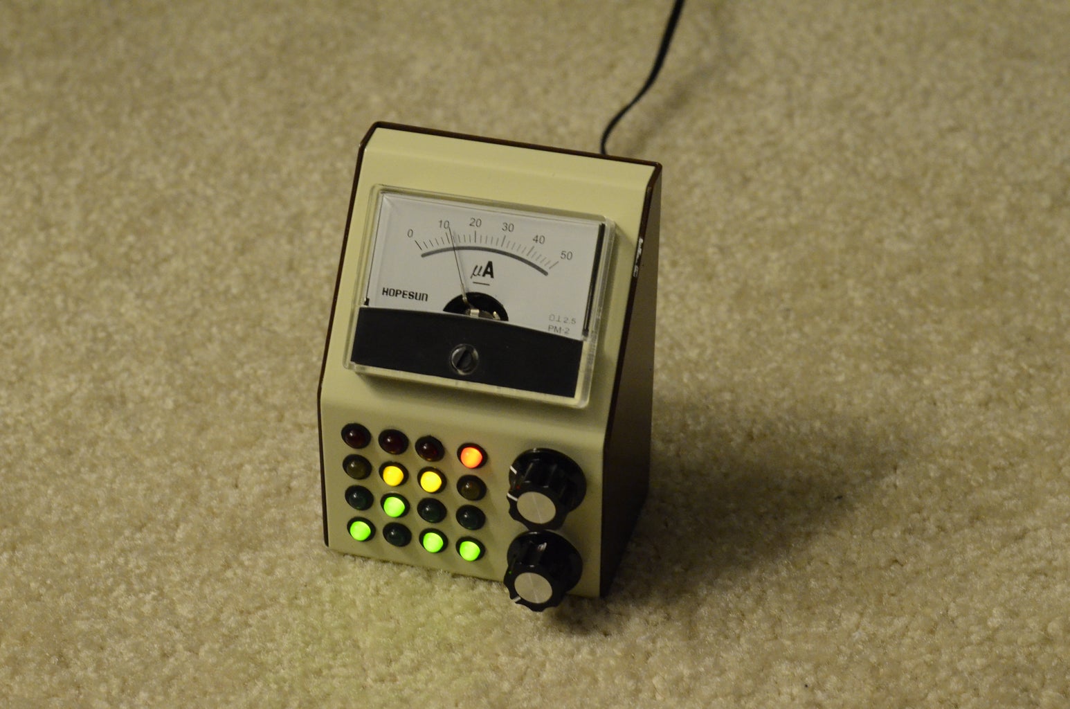
Step 13: The Final Product
After putting all of the components together, you can sit back, marvel at your creation, and get ready to explain how it works to friends until you're blue in the face!
Step 14: Dealing With Inaccuracy
One of the points of this project was to create a clock that is accurate and can be trusted, but if you put the Cwik Clock next to a very reliable clock, you may notice that it is slow/fast by a few seconds over a 24 hour period.
Targeting the Error
As far as I can tell, there's no place in the code where milliseconds go missing, so I'm led to believe that the timing inaccuracies are due to standard error in the crystal clock. My knowledge of how crystal clocks is supremely amateur, but I could be convinced that many factors play into its accuracy, such as supplied voltage, temperature, fabrication process, age of the clock, etc. I'd also assume that if you replaced the crystal clock with another one, you'd observe different behavior (one could be fast, one could be slow). Since there's so many variables, it's useless to try and address the error before the final product is assembled with the final components (hence why this step is after you solder and assemble the Cwik Clock).
Measuring the Error
In order to compenstate for the error in software, we must fully understand our error. The way we'll measure error is by precisely starting the Cwik Clock next to an extremely accurate reference clock which displays seconds (like a computer), and seeing how far off the Cwik Clock is from the reference clock after exactly 7 days.
For example, if the time is currently 8:05am on Monday, go into time-setting mode, set the Cwik Clock to 8:06am, and wait for your reference clock to change to 8:06 before flicking the switch to disable time-setting mode (since we reset the seconds in time setting mode). Leave your clock for 7 days, and when the Cwik Clock reach 8:06am the following week, capture the time on your reference clock and measure the difference.
I recommend a full week because the longer the time ellapsed, the more accurately we can measure the error. Next, there's a hunch that the power source could be responsible for some of the error. If you're powering your device from a 9V DC power source plugged into the wall, power usage characteristics are relatively cyclic with a period of a week. You and your neighbors may use less/more power on weekends compared to weekdays, but by capturing a full week, we're hoping to get an average error, not a daily error that can fluctuate depending on the day of the week.
Fixing the Error
Now that we have a the number of seconds that actually ellapsed (the time on the reference clock) and the time that the Cwik Clock thought ellapsed, we can calculate the error.
In our example above, if after a week on the Cwik Clock the time on the reference clock is 08:06:52, it means we're running slow, with the following accuracy:
accuracy = (seconds the CwikClock thought ellapsed) / (seconds that the reference clock thought ellapsed)
accuracy = (7 days * 24 hour/day * 60 minutes/hour * 60 seconds/minute) / ((7 day * 24 hour/day * 60 minutes/hour * 60 seconds/minute) + 52)
accuracy = 604800 seconds / 605852 seconds
accuracy = 0.998263602
To compensate, change ONE_SECOND in code to 1000 * accuracy, or 998. If you decide to tweak the accuracy after yet another week, set ONE_SECOND to 998 * accuracy (not the initial 1000 * accuracy, since the measurements were taken assuming ONE_SECOND is 998ms from our crystal clock).
Step 15: Future Improvments
My intention is to create a smart alarm for version 2.0 of the Cwik Clock.
I hate waking up to my alarm screaming at me, and I don't trust setting it to a radio station (what if they have a 1 hour moment of silence in memory of the DJ's pet seamonkey that died over the weekend?). Thus, my goal is to create an alarm that:
1) Is pleasant or easy to wake up to. It may not be a sound, but will start subtly and gradually get more persuasive the longer you wait.
2) Will consider REM cycles. The idea is that if you wake up between REM cycles, you will feel more rested than if you got more sleep but interrupted a cycle. The average cycle is 90 minutes, so ideal times to wake up would be after 6 hours, 7.5 hours, or 9 hours after you fall asleep (or any other multiple of 90 minutes). It will respect an absolute latest time you're willing to wake up (which is what you'd set a normal alarm clock to), but may wake you up earlier if it thinks you'll be more rested. The hard part is trying to figure out when you go to sleep without requiring you to sleep while wearing sensors.
This added functionality will require extra pins, but we're basically maxing out the number of digital pins we have on the Uno. There are a few techniques to get around this, one which employs the use of a shift register. As such, the Cwik Clock v2.0 will probably require more complex innards to account for the added functionality.
I've got a few clever ideas on how to accomplish the 2 goals listed above, but you'll have to hang tight to see if/when v2.0 sees the light of day.

Finalist in the
LED Contest with Elemental LED

Participated in the
Maker Moms Contest


