

Introduction: DIY 3D Printed Laser Engraver With Approx. 38x29cm Engraving Area


A word in advance: This project makes use of a laser with a great amount of radiated power. This can be very harmfull for different materials, your skin and specially your eyes. So be carefull when using this machine and try to block every direct and reflected laser radiation to aviod hitting it something outside the machine!
Use protection goggles suitable for the frequency of the used laser.
A while ago I've made a mini laser engraver, base on two cd drives. After that I made a bigger one based on things I had lying around in my workshop ( see my "Quick, Dirty and cheap laser engraver" instructable). The small one works fine but is small. The bigger one is bigger but due to the play in the parts not so accurate.
But now I own a 3D printer I decided to make one from scratch with parts I wil buy and parts I wil design and print by myself. So I did.
I have paid around 190 Euro's for the parts without the laser I allready possessed.
Yes it's tue, this is again a instructable for a laser engraver. But I think that all instructables you can read about a subject, add a lot of info and an other angle of perspective that can help you deside what to to.
And again it's true, you can buy a complete laser engraver for that amount of money (probably a smaller one) but the fun of building it yourself, for me, is priceless as well as knowing exactly how all is put together. And besides that I exprienced a lot of fun figuring out wat the dimension should be for the designs (I admit: for inspiration I have looked a bit on the internet at engravers you can buy as a kit) of the things to print to make it work. It makes you understand the whole thing better.
In this instructable I wil show you what I have purchased, what I have printed and how it's put together to make a 38x29 cm (engraving/cutting size) laser engraver.
I printed all the printable parts with my Davinci pro 3-in-1 printer: the blue parts with PLA and the white things (the distance buses) with ABS.
Printer settings PLA:
- 210 degrees C
- no heated bed
- 0.25 mm layers
- shell thickness (normal, top and bottom surface) 4 layers
- 80% infill (except the "belt holder plates" print those with 100% infill)
- all speeds at 30 mm/s (except non printing and retraction speed at 60mm/s and the bottom layer at 20 mm/s)
- brim 5 mm
- no supports
- extrusion ratio 100%
Printer settings ABS:
- normal ABS settings with 100% infill
Please keep in mind that English is'nt my native tongue and I appologise in advance for any grammatically and spelling mistakes.
Step 1: Bill of Materials

This is the list of things I have purchased:
- 1x aluminum profile 2020 extrusions, length 1 m
- 2x aluminum profile 2040 extrusions, length 1 m
- 1x axel 8mm diameter, length approx 44cm
- 4x aluminum corner joints with corresponding nuts and bolts
- 1x batch of sliding nuts (where I buy it the batch is 20 pcs. You don't use them all)
- 12x nylon wheels 23 mm (inner size 5 mm) specially for the used profiles
- 1 ball bearing, 22 mm outside, 8 mm inside
- 2x GT2 pulley, 8mm hole, for 6 mm wide belt (20 teeth)
- 1x GT2 pulley, 5mm hole, for 6 mm wide belt (20 teeth)
- 1x flexible axis coupler 5 mm - 8 mm
- 2 meters of GT2 timing belt 6mm
- 2x NEMA17 stepper motors (1.8 degrees/step, 4.0 kg/cm) 42BYGHW609L20P1X2, or simular
- 2x stepper motor cables, 1 m (if you gonna use cable guides you need longer cables)
- 4x limit switch, hole distance 10 mm (the printed mounting plate is for that distance)
- 1x Aduino Nano
- 2x StepStick DRV8825 stepper driver with heatsink
- 12x m6 x 30 mm bolts
- 8x m5 x 30 mm bolts, nuts and washers
- 4x m5 x 55 mm bolts, nuts and washers
- 4x m3 x n mm (where n is the value depending of the depth of the m3 holes in the motors and the 7 mm plate thickness + the length of the long distance buses)
- 4x m3 x n mm (where n is the value depending of the depth of the m3 holes in the motors and the 7 mm plate thickness)
- some m4 bolts for the belt holders and the limit switch mounting plate
also needed:
- 1x capacitor 100uF
- 1x resistor 220 Ohm
- 1x led
- 1x push button (motor release switch)
- 1x suitable breadboard
- 1x 12 V power supply or an adaptor, wich delivers enough Amps.
- 1x TTL capable laser, preferably equal to or more than 500 mW. Higher Wattages reduces engraving time quite well! I use a 2 W laser and that does do fine.
And when you done breadboarding:
- 1x Prototyping board / PCB Fiberglass (34x52 holes / 9x15cm) (Or make an etched PCB)
- 1x jack plug 2.1 x 5.5 mm inlet (the part that wil be soldered on the PCB and the adaptor plug goes in to)
Things to print:
- LE3 Feet
- LE3 Test Caliber central distance suport wheels LE3
- LE3 Ball bearing caliber 21.5 22 22.5 mm
- LE3 Distance buses
- LE3 motor and opposite side
- LE3 laser_motor holder
- LE3 belt holder 20x40 frame
- LE3 Limit Switch mounting plate 20x40 frame
- LE3 cable clip 20x40 frame
- **********************added may 11 2021******************************
- **** LE3 motor and opposite side with adjustable axle distance****
- ****
- **** After adusting the distance you can fix the exentric bolt holder in place with
- **** two parker screws. There are two holes per side to do so.
- ****
- **** these can substitute "LE3 motor and opposite side" who has not adjustable axle distance!
- ****
- ***************************************************************************
and, if needed:
- LE3 cable mounts and PCB mount
Step 2: STL Print Files
Attachments
 LE3 Feet.stl
- LE3 Test Caliber central distance suport wheels.stl
- LE3 Ball bearing caliber 21.5 22 22.5 mm.stl
- LE3 Distance buses.stl
- LE3 motor and opposite side.stl
- LE3 laser_motor holder.stl
- LE3 cable mounts and PCB mount.stl
- LE3 belt holder 20x40 frame.stl
- LE3 cable clip 20x40 frame.stl
- LE3 Limit Switch mounting plate 20x40 frame.stl
- LE3 motor and opposite side with adijustable axle distance.stl


Step 3: 3D Printed Parts


These are all the printed parts
Step 4: Tools You Need
Most hardware you need you probably have lying around in your workshop, such as:
- Plyers
- Screw drivers
- Soldering iron
- Tieraps
- A tap and die set
- A caliper
Not much more really. But most important is the possessing of or have access to a 3D printer.
Step 5: Preperations


Cut the profiles in the following lengths:
- the 2020 profile: 2 pieces of 37 cm each
- the 2040 profile: 2 pieces of 55 cm each and one piece of 42 cm.
You can saw the profiles with a hecksaw but if you have access to an Industrial trimmer saw (like I did) you must use that instead. The results are much better.
Now you have 5 pieces of frame. See pic. 1
Next thing to do is to tap M6 thread in all of the 2040 profiles. See pic. 2
These are actually the only preperations you have to make.
Step 6: The Main Frame


Putting the main frame together is easy and straight foreward (pic. 1 and 2). When finished you get a good idea of the size of it.
After that print the feet, "LE3 Feet"(pic. 3), drill out the holes 6mm , and bolt them with 8 m6 bolts to the frame.
As you can see I did not printed the parts completely massive but hollow on one side. This saves a lot of filament and printing time, and it is very strong! The smooth side in or out (pic. 4) makes no difference about sturdyness, it's a cosmetic choise.
Step 7: Make Sure Printsizes Are Correct, and Putting Together the Carriage


It's important to figure out how accurate the printer prints. For that purpose I have made some test calibers:
so what to do:
- print the "LE3distance buses" (white on pic. 2)
- print the "LE3 Test Caliber central distance suport wheels" and the "LE3ball bearing caliber"
- drill out the holes for the wheel axels (5mm bolts) with a 5 mm drill
- left on pic. 1 is the test caliber to determine how big the hole for the ballbearing has to be print to let it fit snugly. There are three diferent sizes: 21.5, 22 and 22.5 mm. These are the values givin in the print design. The hole where the bearing fits best (you have to put some force to it to put it in) is the one you need.
- Right you see the caliber to test the distance between the guiding wheels. It.s important that there is no play between the 2040 frame and the wheels. You can figure that out with this caliber. Simply bolt three wheels with 5mm bolts and the spacers on to it and try out in which distance (58 or 59 mm) the frame moves with some resistance through the wheels.
Note:
in the print designs I have used 22.5 mm for the ballbearing hole and 58 mm distance between the wheels. This works perfectly for me. If these values are not working for you, then you have to tinker the design.
After figuring out the right sizes, and printing the "LE3motor and opposite side", first drill out the holes on both plates.
Put together the carriage (pic. 2).
You need the 2040 frame, 42 cm long and the motor and bearing plates, 4 m6 bolts, 8 m5 bolts and nuts.
- drill out the holes: 3mm for the motor holes, 5mm for the wheel axel holes, 6mm for the holes to fix the plate to the profile
- bolt the two upper wheels on one of the the plates (use 5mm washers between the buses and the wheels, the wheels must turn freely!)
- when resting these wheels on the frame, assemble the lower two wheels as wel
- do the same with the other side (on pic. 2 the motor plate is in front and the bearing plate in the back)
- bolt with 4 m6 bolts the 2040 frame between the plates
Now you can move the carriage. It's ok if you feel some resistance, it tels you that there is no play. The motors are strong enough to handle with that.
This assembly is in fact a general way of how to put the rest of this machine together. From now on I shall therefore be less expanded and will point out only important things. Pictures also say alot.
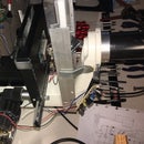
Step 8: Axel and Motor


- Use the 4 long distance buses to bolt the motor on the plate (you have to figure out the right length for the bolts, it depends on how deep the holes in the motor are)
- put the bearing in place
- push the 8mm axel through the bearing and at the same time put the 8mm pulleys and the 5mm-8mm flexible axis coupler on the axis
- fasten everything in place so that the pulley teeth are exactly above the slot of the frame
Step 9: The Laser/motor Holder and the Belts


The laser/motor holder:
- Print "LE3 laser_motor holder"
- Print "LE3 belt holder 20x40 frame"
- Drill out the belt holders at 3.2 mm and tap 4mm thread in the holes
- drill out the holes of the laser/motor holder to the appropriate diameters. The extra holes on the laser side are for mouting a universal laser mounting plate I did not designed yet.
- assemble the laser/motor holder complete
- temporary take away the 2040 profile of the carriage
- slide the profile trough the wheels. It's ok if you have to push fairly hard to put the profile trough. When I hold my frame perpendicular to the ground, even with the motor assembled, gravity will not move the laser/motor holder.
- put on both sides a belt holder
- put the profile with the laser/motor holder back again.
On pic. 1 you can see how it's put together (the picture was taken in a later stage. I had forgot to make one earlier). Don't forget the washers between the buses and the wheels! Please don't mind the laser, this is merely a test assembly.
The belts. First the one in the laser holder:
- lead the belt under the wheels and over the pulley like on pic. 2
- lead the belt on both sides under the belt holders (make sure you have enough belt length so that you can grab a piece of belt on both sides)
- on one side push the belt holder as far as possible to the side and fasten the bolt (it's not nessecary to fasten it very tight)
- now do the same at the other side and at the same time pull on the belt so that there is a reasonable tension between the pulley and the wheels
For the two belts of the carriage (pic. 3 and 4) do the same, but with the difference that you only have to turn away one foot (take away the top bolt and loosen the bottom one) and insert two belt holders on one side. Now you can slide the other one under the carriage to the other side. Also make sure that, after tensioning the two belts, the carriage is completely at right angles!
ps.
if you print the belt holders at an earlier stage you can insert them in the frame before assembly.
Step 10: The Limit Switches + Holders


First print:
- LE3 Limit Switch mounting plate 20x40 frame
- LE3 cable clip 20x40 frame
On pic. 1 and 2 you see the assembled limit switches on the main frame. The distance between them is approx. 45 cm (38 cm engraving distance + 7 cm plate width)
On pic. 3 and 4 the limit switches on the crossbar, distance: 36 cm (29 + 7). After assembly check if the switches are situated properly (no mechanical collisions).
All the mechanical work is pretty much done now.
You can wire the switches already and use the cable clips to secure the wires in the lateral frame slots.
Step 11: The Electronics


- Pic. 1 shows schematicly the connections between the parts
- Pic. 2 how the breadboard connections should be.
- Pic. 3 and 6 the breadboard in real live
- Pic. 4 the wire side of the prototyping board i've made
- Pic. 5 the part side. Notice all the female header connections for the Arduino, the driver boards and all the wire connections. These connections let switching boards (when nessesary) be more easy.
I have designed moutning brakets for the 9x15 cm prototyping board so you can bolt the board to the 2020 profile. These brakets is a part of the "LE3 cable mounts and PCB mount" print file (pic.7 and 8).
There are 3 connections on each driver board to control the step resolution: M0, M1 and M2. With these connections you can determine the step resolution depending on how to connect these to +5V. There for I've made on the prototyping board jumper lines for each of the 3 lines on the two divers. They are in the yellow circles on pic. 5.
With these jumpers you can set easely the step resolution:
M0 M1 M2 Resolution
- low low low Full
- high low low Half
- low high low 1/4
- high high low 1/8 (this is the setting I use and are drawn in the pics)
- low low high 1/16
- high high high 1/32
Where high means: connected to +5V (closed jumper line).
You won't find these jumpers on the breadboard or schematic, but you get the idea and can implement them yourself if nesesary.
You can omit these jumpers and set the step resolution permanently to the desired step resolution. Until now I haven't change the jumper settings: 1/8 resolution works fine!
You also not find the switch on pic. 5 (top right corner). This switch I've implemented toggles between D12 and D11 on the Arduino board for steering the laser, resp. M03 and M04 (Gcode). But I find out that with the right programs you don't have to use M03 any more so I have leave it out of the plans. Instead the TTL line is directly connected to D11 (M04).
Ps.
please note that, on the scematics, the two connectors (5 wires and 4 wires) were necesary for me because I had build my laser system myself with a seperate cooling fan. But if you have a laser module and you don't want to regulate the power to the laser. You only need the 3 upper lines of the 5 line connector and the power should be coming from the power supply that comes with your laser.
Step 12: Software


Used programs for the purpose of this instructable:
- GRBL, version 1.1 (arduino library)
- LaserGRBL.exe, program to send sliced pictures or vector graphics to your engraver/cutter
- Inkscape, vector drawing program
- JTP Laser Tool V1.8, plugin needed for Inkscape to make a Gcode file for LaserGRBL
- Notepad++
On the internet you can find plenty information about how to install, download and use of these programs.
The first thing you have to do is alter the config.h file of the GRBL library:
- after downloading GRBL v1.1 open config.h with Notepad++ (you can find config.h in the directory GRBL)
- find the lines you see on pic. 1,2 and 3 and change them according to the right part of the picture (left on the pics you see the original lines and right the altered ones)
- save the file
Now load the GRBL library into your Arduino nano controller:
- connect your Arduino to your pc
- start your Arduino program
- choose Sketch
- choose Import library
- choose add library
- go to your directory where GRBL is situated and click (not open) on the GRBL directory (the directory where you altered the config.h file)
- click open
- Ignore the uncatagorised bla bla bla message and close the Arduino program
- Go to the ...GRBL/examples/grblUpload directory and start grblUpload.ino
- now the Arduino program starts and compiling begins. When finished, Ignore the too little memory space message and close the Arduino program.
On this stage the Arduino board is loaded with GRBL and the settings for Homing and the limit switches are correct.
Now you have to let GRBL on the Arduino board know what speeds, dimentions etc. are nesesary to make your engraver go.
- connect your Arduino to your pc
- Start laserGRBL.exe
- click on the connect button (right besides the baud rate field)
- type $$ in the send command field (below the progress field) and press [Enter]
- Change the values according to the list on pic. 4. Just type the lines who has to be changed in the send command field (below the progress field). For instance: type $100=40 [Enter]
- Repeat this for all the line to change.
- after that you can type $$ again to see or all chances are correct
While you perform the testrun, see below, you also have to adjust the amount of Amps that goes to the motors. You can turn the little trimmer on both stepstick boards to do that, but disconnect the board from power before you do. Download and read the stepstick datasheet! Adjust the trimmers step by step until the motors run smooth and never loose a step. The trimmers on my boards are approx 3/4 turned right.
Now you can testrun the engraver to see or all the movements works ok and, very important!, if the limit switches are working. If a limit switch is activated the machine goes in an error state. In laserGRBL you can read how to solve that software-based, $x or something like that, and now the motor release switch come in handy: in the error state probably one of the switches is still activated, now press the motor release switch and pull the desired carriage a little bit away from the switch to release it. Now you can "reset" and "homing" the machine.
Basically you are now ready for your first calibration run.
Step 13: Calibrate
The following procedure is an excerpt of a part of my "Quick, dirty and cheap laser engraver" instructable and can be of help if you have deviations in the measurements of your engraving output.
"For the calibration of $100 (x, step/mm) and $101 (y, step/mm) I did the following:
- I filled in the value 80 or so for both $100 and $101
- then I draw a square of a given size, say 25mm in Inkscape and start to engrave **
- The first result shall not be a square with the right size, 25x25mm.
- Start with the x-axis:
- let's say that A is the value you want for $100 and B is the value of $100 (80) and C is the value in Inkscape (25), and D is the value you measure on the engraved square (40 or so)
- then A = Bx(C/D)
In this example the new value for $100 (A) is 80x(25/40)=80x0,625=50
The same can you do with the y-axis ($101).
The result is fairly accurate. If you use exactly the same motors, belts and pulleys for the x- and y-axis the values of $100 and $101 shall be the same."
** If you make a calibration square in Inkscape, use the JTP Laser Tool V1.8 plugin to make a (vector) Gcode file that you can load into laserGRBL. Make sure you fill in M04 to switch on and M05 to switch off the laser in the JTP Laser Tool V1.8 plugin!
Step 14: Ready!


If all was going wel you now have engraved a square with a size of exactly 25mm.
Now you can engrave/cut anything you like: grayscale pictures, vector drawings, patterns to cut etc. And that with great accuracy!
pic.1, the bottom characters are very small (distance between two lines on the ruler is 1mm)
pic.2, some first gray scale results.
pic. 3, Pretty accurate!
The video shows the engraver at work.
Step 15: Last Step


Now all is working fine you can start with fine tuning the contraption with cable guides and a nice PCB. I have created some cable guide mounts that you can print and use to attach cable guides (print file "LE3 cable mounts and PCB mount").
If you do make use of cable guides then the 1 meter long motor cables are not long enough and you have to buy longer cables or make cable extensions (that's what I did). On the pics you see how I made use of the cable guides (and mounts). And to be honest, cable guiding makes it a lot easyer to engrave because you don't have to be afraid of burned trough cables or cables stuck between parts etc.
I hope that this instructable is inspirational for you and also be a source of information for making a laser engraver. I have experienced a lot of fun designing and building it and I know you should to when building this thing.
Happy build!


