

Introduction: DIY Arduino 3D Laser Scanner


FabScan is an open-source, do-it-yourself 3D laser scanner.It started out as a Bachelor's thesis by Francis Engelmann, supervised by René Bohne. You can find official project here.
I made my own box from MDF hood sheets and use different hardware parts.I decided to make this guide to show to you my work.
All credits for Arduino software and computer application goes to FabScan team, so thank you very much for this great open source 3D laser scanner!
Dev: Francis Engelmann Official page: hci.rwth-aachen.de/fabscan
Q & A at http://www.ardumotive.com/arduino-3d-scanner.html
Let's get started!
P.S. Please, if you like my project vote for me. Thanks!!!! :)))
Step 1: What You Will Need


Hardware of official FabScan project:
- Arduino UNO
- A4988 Stepper Motor Driver
- FabScan-Shield - 3D Laser Scanner
- 5mW Laser Module - Red Line
- Bipolar Stepper motor - NEMA 17 (200 Steps)
- 12V - 1A power supply
- Web camera Logitech C270
To build the box you will need 4x sheets of MDF wood, size 600mm x 300mm - 5mm. You can find more info here.
Hardware that I have used:
- Arduino UNO
- Stepper motor - NEMA 17 (200 Steps)
- L298N Motor Driver Module
UPDATE: Use A4988 stepper driver - 5mW Laser Module - Red Line
- 12V - 2A power supply
- Web camera Logitech C270
I advised you to select the official FabScan hardware part list.
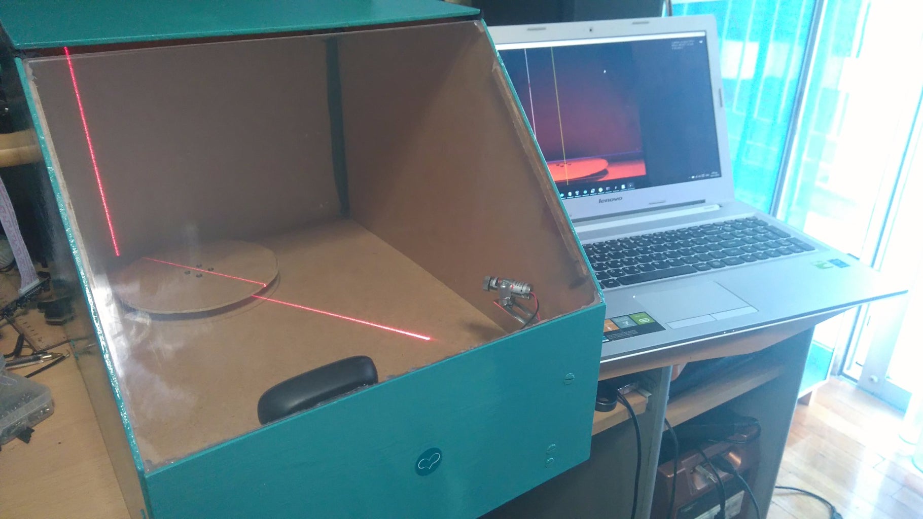
Step 2: Build the Box - Gallery of My 3D Scanner


I used a Dremel cutting tool and my imagination to build my own box. This it not an easy procedure because the camera, stepper and laser module must be on the correct position to successful scan an object. If you want to make your life easier you can also buy cutted parts for only 35 euros from here.
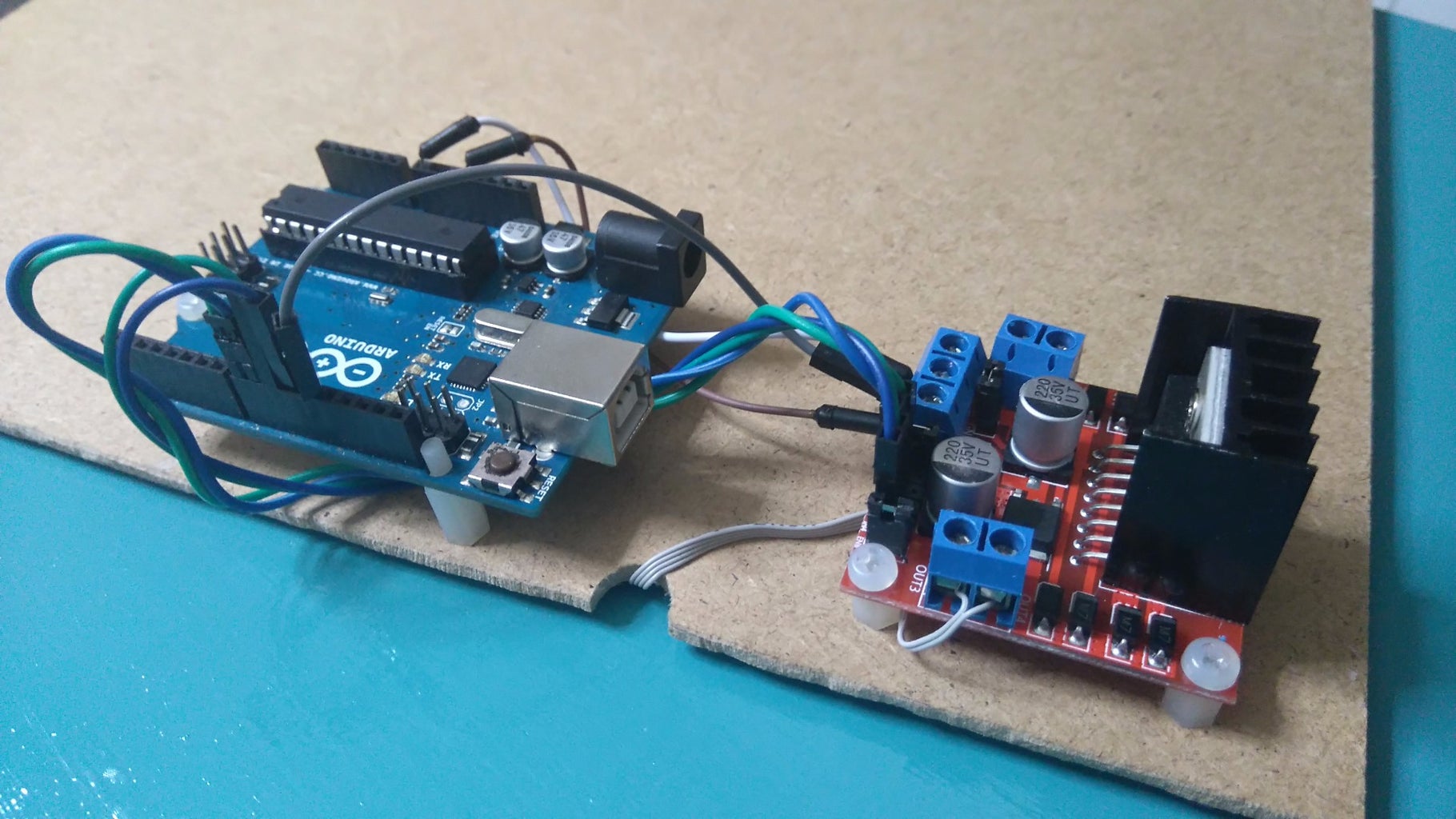
Step 3: Hardware Connections


The connections are pretty easy:
Attach the FabScan shield on Arduino and the A4988 stepper driver on the first stepper position of it. Connect the stepper on output pins and the laser module to analog pin A4. Finally connect Power supply and usb cable. You can also find a very usufull assembly tutorial here.
Custom hardware:
If you decided to make this with my hardware parts then you have to connect the L298 stepper motor driver to Arduino pins 10,11,9,8 (you can change those pins) and laser module to Arduino pin A4. Finally connect the power supply and usb cable.
Step 4: The Code
Here's the official FabScan code, embedded using Codebender!
Try downloading the codebender plugin and clicking on the "Run on Arduino" button to program your Arduino board with this sketch.
And that's it, you've programmed your Arduino board directly from your browser!
(https://codebender.cc/sketch:186175)
If you decided to make this with my hardware parts, click the Edit button and:
- Add lines
#include
const int stepsPerRevolution = 200; // change this to fit the number of steps per revolution
// for your motor
Stepper myStepper(stepsPerRevolution, 10, 11,8,9);
- Replace step() function with:
void step() {
myStepper.setSpeed(1);
myStepper.step(1);
}
Step 5: Software (computer Side)


We will use the "FabScan Ubuntu Live DVD" image that was created by Mario Lukas. You can download it from here, this image has preinstalled the FabScan software. You can write the image on a flash drive with Win32DiskImager (download link) and use it without installing linux os on your system.You can find more options for other operating systems here.
Important note! If you use the "Try Ubuntu" option make sure to save your files before shutdown the computer!
See the above images and follow the steps:
- Select SerialPort
- Select Camera
- File - Control Panel
- Click on detect laser (don't put any object in scanner yet) and select 'enable'
- Click on "Fetch Frame" and make sure that the blue horizontal line touches the top of the turning table and the yellow horizontal line touches the bottom of the turning table. Also the yellow vertical line should pass through the center of the turntable. A non aligned camera will result in distorted scans!
After setup close control panel window, put an object inside scanner and press the start scan button.
Tip: You can change the configuration.xml file of FabScan by following this guide.
Saving 3D image:
When scanning procedure is completed you can save the scanned 3D object as an 3D pointcloud .pcd or .ply file. You can also save it as an 3D stl file but this doesn't work to all platforms. If you would like you can also open an older scanned object by selecting File - OpenPointCloud.
What next?
You can use MeshLab for processing scanned object and then print it with a 3D printer!
File processing with MeshLab:
1. Make sure that you saved object as an .ply file.
2. Open file with MeshLab
3. In MeshLab, compute the normals (Filters/Point Set/Compute normals for point sets)
4. Then reconstruct the surface using poisson reconstruction (Filters/Point Set/Surface Reconstruction: Poisson)
The end :D
Many many thanks to FabScan team!!!

Runner Up in the
Robotics Contest

Runner Up in the
Tech Contest


