

Introduction: DIY Arduino Wordclock


My version of a word clock will not feature a 12×12 LED-Matrix display. Instead it’s made with LED strips and only the significant words on the clock can light up. With this method you can’t display custom messages, but the whole build won’t cost you as much either.
This instructable is an almost exact copy of my article, which is published here.
Step 1: Gather the Necessary Materials
The case
For the case you’ll need the following items. You should be able to get most of these components in your local hardware store (All measurements in mm!):
1. Acryl/Glass front panel (270×270 [mm])
2. Lasercut watch–face (1,5 mm black matte cardboard)
I ordered it from ponoko.com
3. Wood:
2x 300x80x15 [mm]
2x 270x80x15 [mm]
2x 270x40x10 [mm]
2x 250x40x10 [mm]
4. Plywood panels
2x 270x270x5 [mm]
5. Foam-Boards
Will be used as a spacer and to make up a grid for the words on the clock, so the light doesn’t bleed through to other letters that are not meant to be illuminated. These can be hard to find, I got them from amazon.
The electronics
For the electronics you’ll need:
1. LED strip with WS2812B or similar integrated controller
1 meter (60 LEDs)
2. 330 ohm resistor (or something close to it, just for short-circuit protection)
3. RTC Modul
I got this one from banggood.com
Important!
You can use any LED-strip you want, as long as the LEDs can be addressed separately or you build your own controller, that switches on the separate segments. I’ve compiled a list with similar LED-strip controllers. You can download it here.
Step 2: Downloads and Watchfaces


Stencil font
First you need to find a nice monospace, stencil font. Which means, that all the characters have the same width and are completely connected. Unfortunately, I didn't think about that when I built my clock, so some letters are missing their inner parts. However, I like this font. But feel free to use any font you like.
The watchface
Next you'll need to create a watch-face. For this process I simply typed out 12 lines of gibberish consisting of 12 characters per line. Afterwards I added the necessary words (It is, quarter, half, one, two, ..., o'clock and so on). (see fig. 1).
After that was done, I copied all my text and pasted it into photoshop. You can also use GIMP here, if you don't have photoshop. In photoshop you need to change your font to the stencil font you downloaded earlier and lay everything out, so that it looks nicely on a 270x270mm image (this will be the size of our front-place), as shown in figures 2 and 3.
Afterwards convert the text to a path and export everything as a vector-graphics for laser-cutting. See your laser-cutting service's guidelines on how to do this properly, because this varies from service to service.
The firmware
Simply download it here. You'll need this later and I'll discuss it later in this instructable.
Step 3: Assemble the Case


The complete case is made out of two squares and the inner one should fit perfectly into the outer square. Together they form the completed case. The inner one acts as a spacer and mounting place for the LED-boards. Glue the wood pieces together like shown in figure 1.
There should be a 250×250 blank space in the center of the case. This is, where the foam separators will be placed later. I recommend, that you build the outer shell first and then use the front-plate and the watch-face as guides when building the inner frame, so you get a little lip where these two components can be mounted later in the process. This way, they will be flush with the edges of the wooden case and it will look great when finished, as displayed in figure 2. Don't forget to account for the thickness of your laser-cut watch-face here. Simply add that, depending on the chosen material.
From the back, the case should look like mine shown in figure 3. Don't forger to make a cutout for either a dc-jack or a cable somewhere on the case, preferable on the bottom side.
Step 4: The Electronics


This was the part, that took me a long time to do. It was not hard to do, but you’ll have to do all the wiring by hand, so get ready for at least two hours of soldering!
First, take one of the two plywood panels and your front-face and align them, so that the front-face sits on the panel. Afterwards grab a pen and transfer the letters, that you want to light up later, to the plywood panel. It should look like shown in figure 1 afterwards. (Note: I used a foam-board instead of the plywood, but I'd recommend using wood, because the foam tends to melt when soldering and it is a potential fire and health danger).
Afterwads lay out the LED strip on this panel. Try to evenly distribute LEDs over the words. I used all 60 LEDs that came on the strip, but you could use less, if you want to. However, the more you use per word, the better it will look at the end, because all the letters of that one word will light up evenly. Figure 2 shows how I distributed them.
When you are happy with the layout, peel off the protective film from the back of the LED-strip and mount the LEDs. Try to place them centered on each word. If your strip is not a self-adhesive one, use some regular glue and let it dry.
Make sure, that you place them in the right direction. My strip had a little arrow on it, indication the way, that the control signal will take (see fig. 3). Align all the strips, so that the arrow always point in the same direction.
After this is done, you’ll need to drill some 2mm holes. At both sides of each LED-strip drill three holes near to the copper contacts on the strip, as shown in figure 4. From the back, the mounting-board should look like mine in figure 5.
Now comes the tricky part: You’ll have to connect the LED-strip pieces together, so that they form one long strip again. That means: Connect the LED-strip pieces in each row together (GND -> GND, 5V -> 5V, Data -> Data).
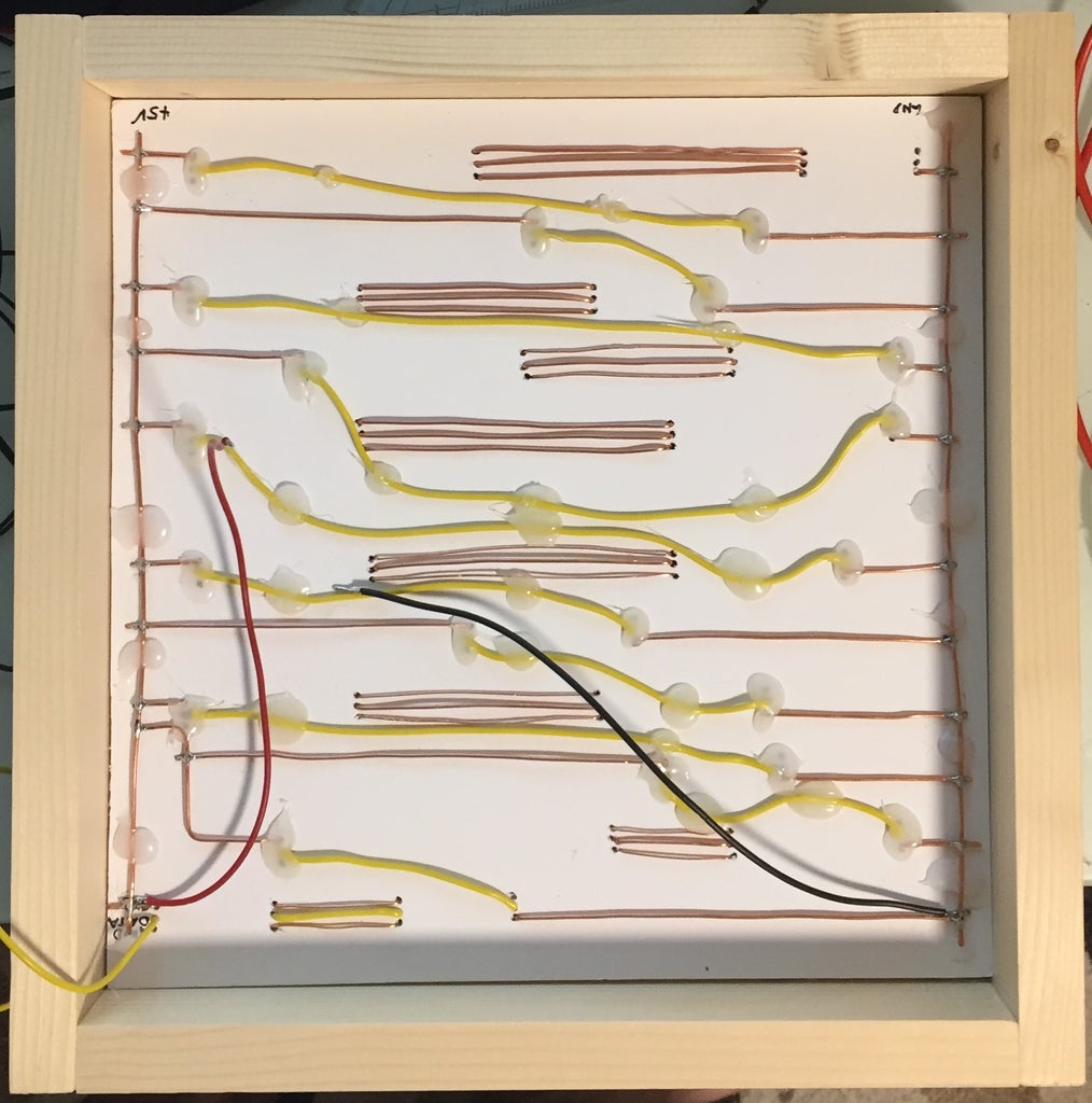
As you can see in figure 5, I connected all the power lines and I made a common +5V and common GND rail on the left and right of the mounting-board. So the strip-pieces are connected together in one line and the last piece of each line is connected to GND on the left and each first piece of a line is connected to +5V.
Afterwards I connected the Data lines of each strip piece of one line together and the last output on a line to the first input of the next line. Then I test-fitted the panel in the case. This can be seen in figure 6.
I used flexible yellow wires to connect the end of a line with the next one and hard-copper wires to make the connections between the LED-strip pieces, that are on the same line. Afterwards I tested the connections by running the test-script and when I saw that everything worked, I secured the yellow wires with hot glue, so they don’t fly all over the place in the case and I added a red and black wire for the power rails.
If you used a DC-Jack for your power-connection, connect it now. I used a phone-charger and wired it in place.
Step 5: Final Assembly


When you made sure, that everything works, mount the board with the LEDs in the case, so that the LEDs face forwards. It should look like this displayed in figure 1.
You can either secure it with screws or just use glue. I settled with the second option, as I don’t plan to remove it again.
After this was done, I started creating the foam-grid that will prevent unwanted letters from lighting up on the front face. So first I cut out eleven 250 x 40 mm pieces out of the foam boards and glued them onto the LED board. Glue these in-between the single lines of text on the front-face and your build should look something like mine shown in figure 2.
Now cut the foam into smaller pieces, that go between the lines and place them where necessary. It should look like mine in figure 3.
This way you create single cells for each word, that will light up in the end. After this is done, let everything dry and cut out a 250 x 250 mm piece of parchment-paper or something that’s similar to it. I used it to diffuse the light coming from the LEDs. place it on the foam-grid and secure it with some drops of glue. Try not to place it on the wooden parts.
Afterwards glue the laser-cut front face into place and then finish it off with the glass front-face. Remember to remove any protective films. The finished product should look like figure 4.
Now put in all the electronic-components that are left and make the necessary connections. The data-line of the LED-strip is connected to my Arduino on its 2nd pin (pin 2) and I added a 330 Ohm resistor for extra protection.
Then connect the RTC-Module to the Arduino’s SDA and SCL pins and to 5V and GND on the Arduino.
Afterwards close the case up with the remaining plywood panel and you’re done with the case!
Step 6: The Firmware
For the firmware I used the fastled and Sodaq-DS3231 libraries for Arduino.
This firmware will only work correctly if you use the same LED-strip controller, as I did. If you want to use a different one, you might need to change the code, so that it fits your parts. I tried to make the code as easy to understand as possible, so you can quickly change it according to your front-face or LED arrangement. If you only used a different LED-controller, you should be good by only changing this line in the setup()-Method:
FastLED.addLeds(leds, NUM_LEDS);
However, if you made a different front-plate, change the numbers of the LEDs, that are defined in the beginning of the program. I think the code should be relatively easy to understand and I added comments.
I admit, that the program is not nicely written (everything is hard-coded), and it’s by no means optimized, but I tried to keep is as simple and easy to understand, as possible.
Step 7: Conclusion

This was my first instructable and I hope you liked it. Like mentioned above, I also have a website where I post more interesting stuff like this. Feel free to visit it.
Also there's a video attached in the first step, if you prefer to watch it, instead of reading.
With this instructable I wanted to show you, that it’s still possible to build a cheap word clock at home without any professional tools or materials. Well, OK you’ll still need a laser-cut front-face, but you could do it yourself if you have the patience and time to cut out each letter individually.
The best thing about this is: From the outside, nobody can see how simple it is from the inside, so you can still pretend to be that engineering mastermind, when people come visit your home and even if you don’t plan to do this, you’ll still have a nice way to represent the current time!

Participated in the
Microcontroller Contest


