

Introduction: DIY ESP32 Bluetooth GamePad for Android, PlayStation and PC


In this project, we will first see how to build a breadboard gamepad circuit, and how you can communicate the circuit as a gamepad with an Android device, TV Box, PlayStation, and Computer. Next, you'll see what you can do by assembling a printed circuit board with a Bat-themed design and using both a Bluetooth gamepad and other communication options.
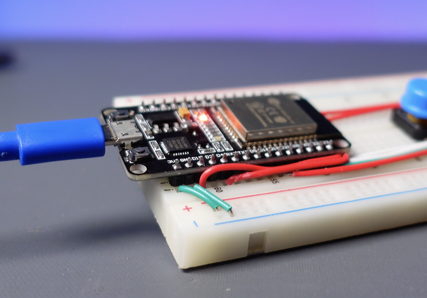
Step 1: Doit ESP32 Devkit V1 Development Board

On the circuit side, I preferred the low-cost Doit ESP32 Devkit V1 development board, which offers wireless communication options such as WiFi, Bluetooth, and ESP-NOW. The ESP32 board model used in the project has a total of 30-pin I/O. Some models have 36-pin I/O and are longer in size. Doit ESP32 Devkit V1 Board can operate with a supply voltage between 4V to 12V via a VIN pin. More detailed information can be found here: https://lastminuteengineers.com/esp32-pinout-reference/
Step 2: Build a Circuit on the Breadboard
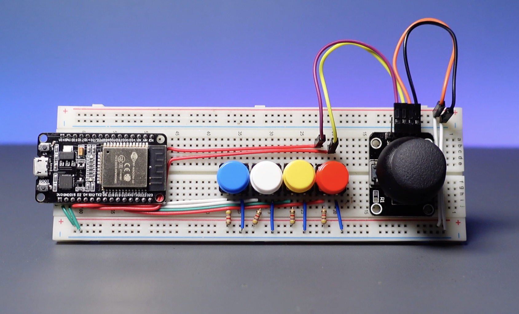


Besides the ESP32 development board, a joystick module, button, resistor, and some wires are required for the gamepad circuit.
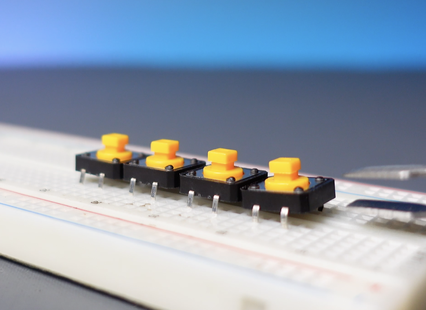
- Push Button Switch 12mm With Round Cap
- 4K7 Resistor for Buttons
- XY Joystick Module
- Doit ESP32 Devkit V1 development board
- Breadboard
- Jumper Wires
Step 3: ESP32 Development Board Setup for the Arduino IDE


To work with the Arduino IDE, we need to set up the ESP32 board. Here are the requirements and steps:
- Download and install the latest version of the Arduino IDE from the official Arduino website.
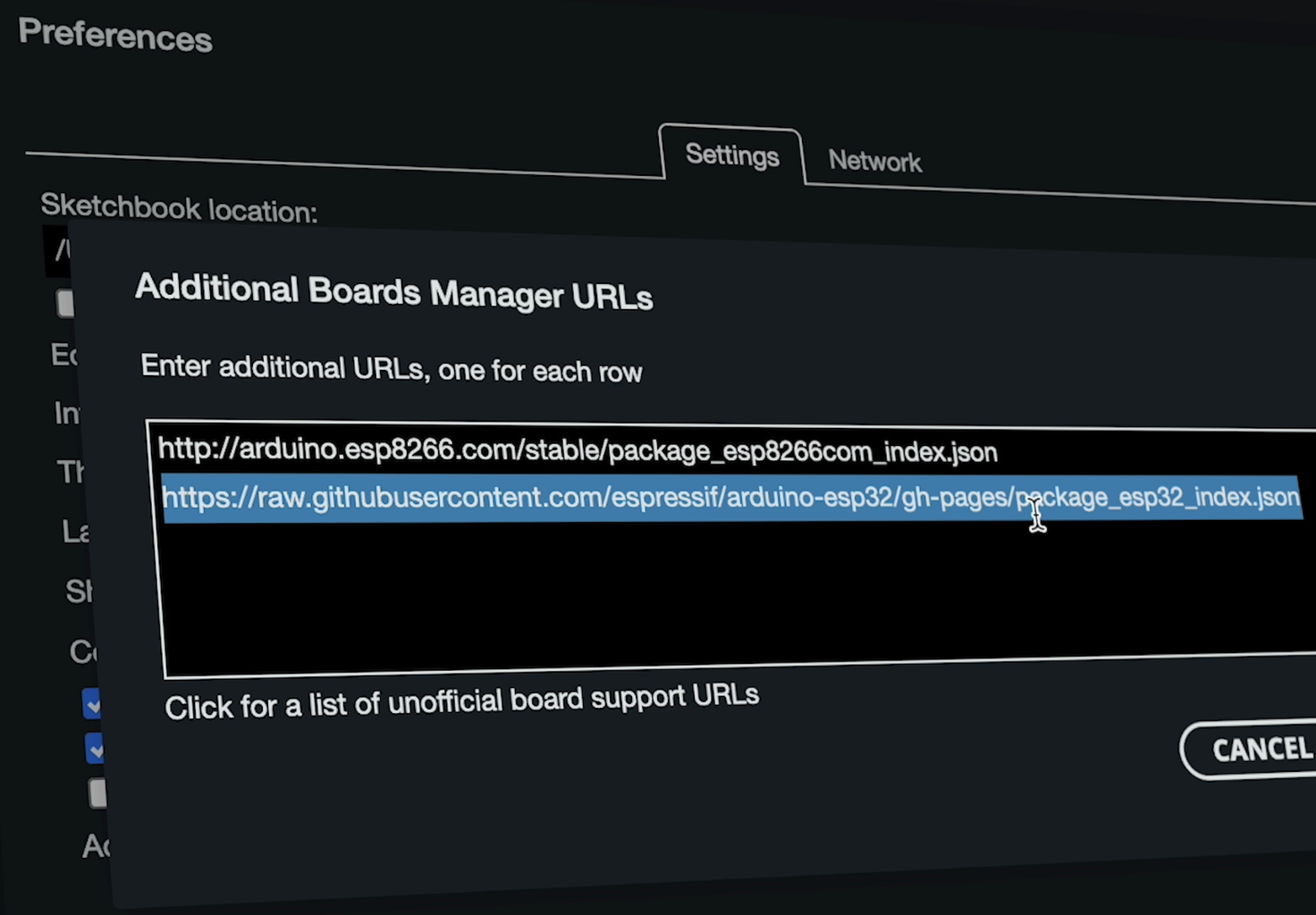
- Open the Arduino IDE and go to "Preferences" > "Board Manager URLs", paste the shared ESP32 package link, and click the ok button.
- Navigate to "Tools" > "Boards Manager."
- Search for "ESP32" in the Boards Manager and install the ESP32 boards.
- Select the appropriate ESP32 board from the "Tools" > "Board" menu.
Additional Boards Manager URL:
https://raw.githubusercontent.com/espressif/arduino-esp32/gh-pages/package_esp32_index.json
Step 4: BLE GamePad and NIM BLE Library for Source Code


The source code includes a popular library called "BLE GamePad". If you go to the GitHub page of the library, you can find detailed explanations and examples.
Go to “Add Library” search for the “BLE GamePad” library and install it. This library also needs the library named “NIM BLE”. If the libraries are installed, let's take a closer look at the source code now.
Step 5: GamePad Source Code
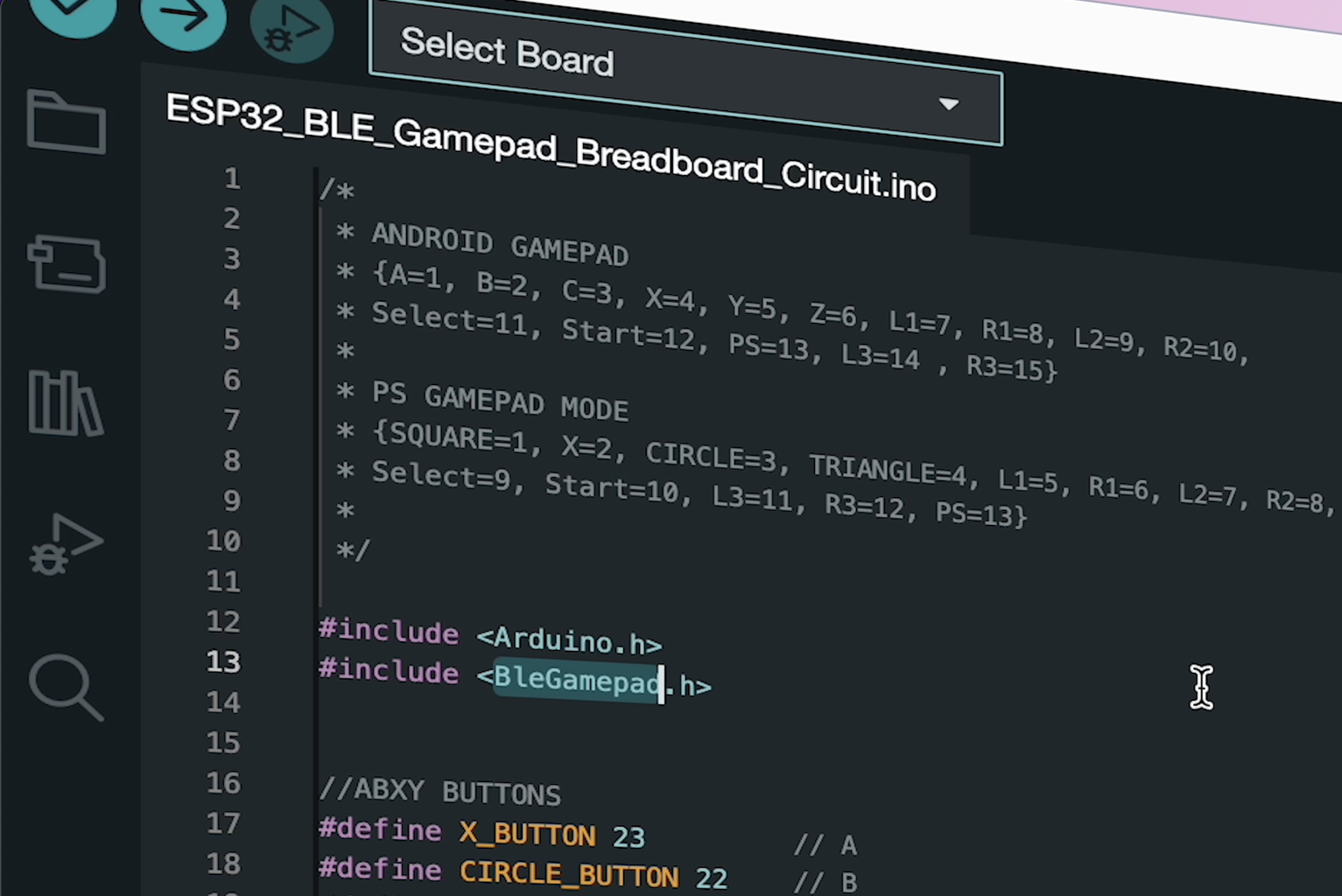

The shared GamePad source code contains a total of 13 buttons, the buttons define the key functions of a standard GamePad. Also, the source code offers three GamePad modes.
This description block contains the key names of the mods as well as the button numbers for the different GamePad mods. Each key name has a corresponding pin number.
/*
 * ANDROID GAMEPAD
 * {A=1, B=2, C=3, X=4, Y=5, Z=6, L1=7, R1=8, L2=9, R2=10,
 * Select=11, Start=12, PS=13, L3=14 , R3=15}
 *
 * PS GAMEPAD MODE
 * {SQUARE=1, X=2, CIRCLE=3, TRIANGLE=4, L1=5, R1=6, L2=7, R2=8,
 * Select=9, Start=10, L3=11, R3=12, PS=13}
 *
 */
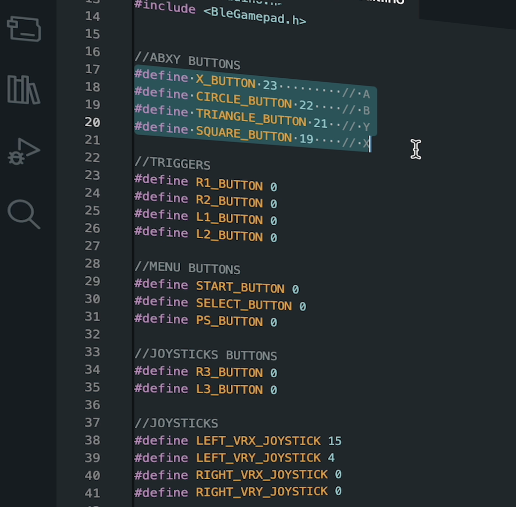
The array "Buttons Pins" represents the physical button pins used on the development board. The constant "Number Buttons" specifies the number of buttons and contains the value of the pin each button is connected to.
int buttonsPins[NUM_BUTTONS] = {X_BUTTON, CIRCLE_BUTTON, TRIANGLE_BUTTON, SQUARE_BUTTON,
                          R1_BUTTON, R2_BUTTON, L1_BUTTON, L2_BUTTON,
                          START_BUTTON, SELECT_BUTTON, PS_BUTTON,
                          R3_BUTTON, L3_BUTTON};
The "Android GamePad Buttons" array contains an ordered list of buttons used in Android GamePad mode. A number is assigned to each button. For example, button "A" is number 1, and button "B" is number 2.
int androidGamepadButtons[NUM_BUTTONS] = {1, 2, 3, 4, 8, 10, 7, 9, 12, 11, 13, 15, 14};
The "PS GamePad Buttons" array contains the list of buttons used in PlayStation GamePad mode.
int PS1GamepadButtons[NUM_BUTTONS] = {2, 3, 4, 1, 6, 8, 5, 7, 10, 9, 13, 12, 11};
The "PC GamePad Buttons" array contains the list of buttons used in Computer GamePad mode.
int PCGamepadButtons[NUM_BUTTONS] = {1, 2, 4, 3, 6, 8, 5, 7, 10, 9, 0, 12, 11};
The "GamePad Mode" variable contains the current GamePad mode. By default, Android mode is assigned, but this value can be changed later in the code.
GamepadModes gamepadMode = ANDROID;
Let's update the source code according to the components found in the breadboard circuit. There are 4 buttons and a Joystick module in the circuit, I will prefer the "Android Gamepad" mode to test the circuit. Define the pins of the components on the circuit, which the key function on the GamePad should call, and update the pin numbers. Then upload the source code.

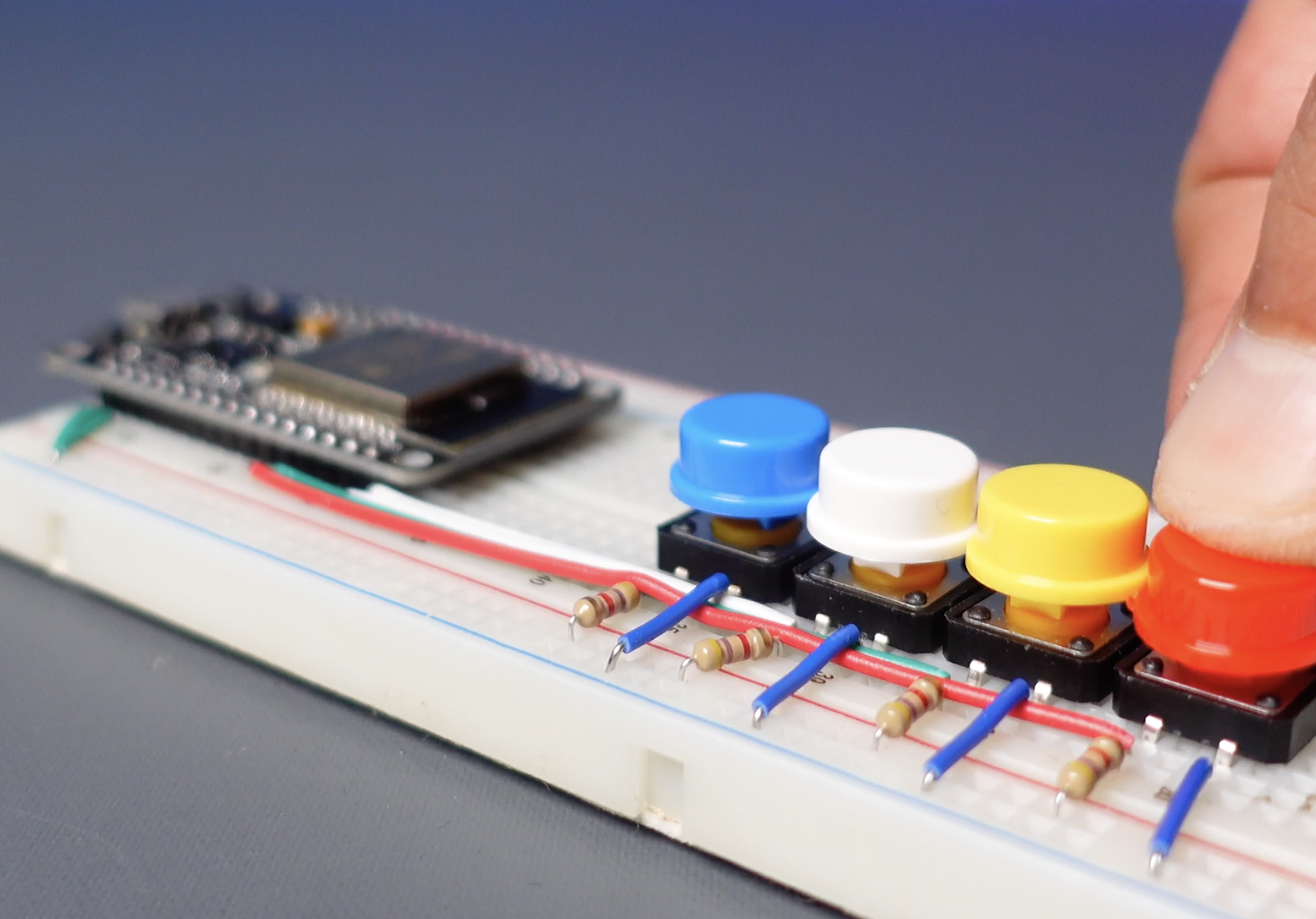
Step 6: Testing the Breadboard Circuit Using the App


I will use the Android application called “GamePad Tester” to view and test the Button and Joystick functions.
- Install the app, then turn on the Bluetooth connection and connect to the ESP32.
- Open the app, go to "Android GamePad Tester" and complete the test of the components on the circuit.
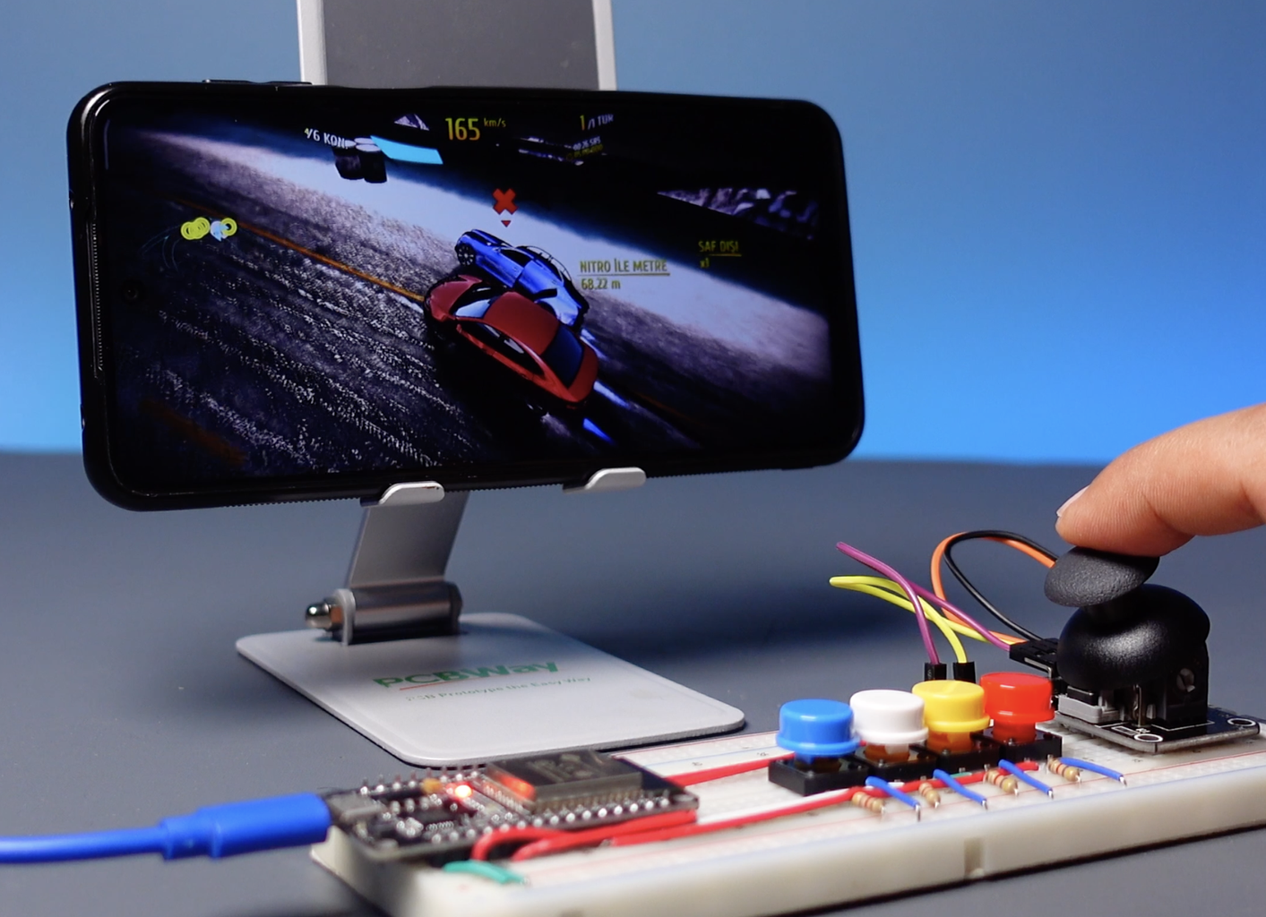
Then, let's make a real test of the circuit through a game. I installed a car racing app, and now it's time to test the circuit!
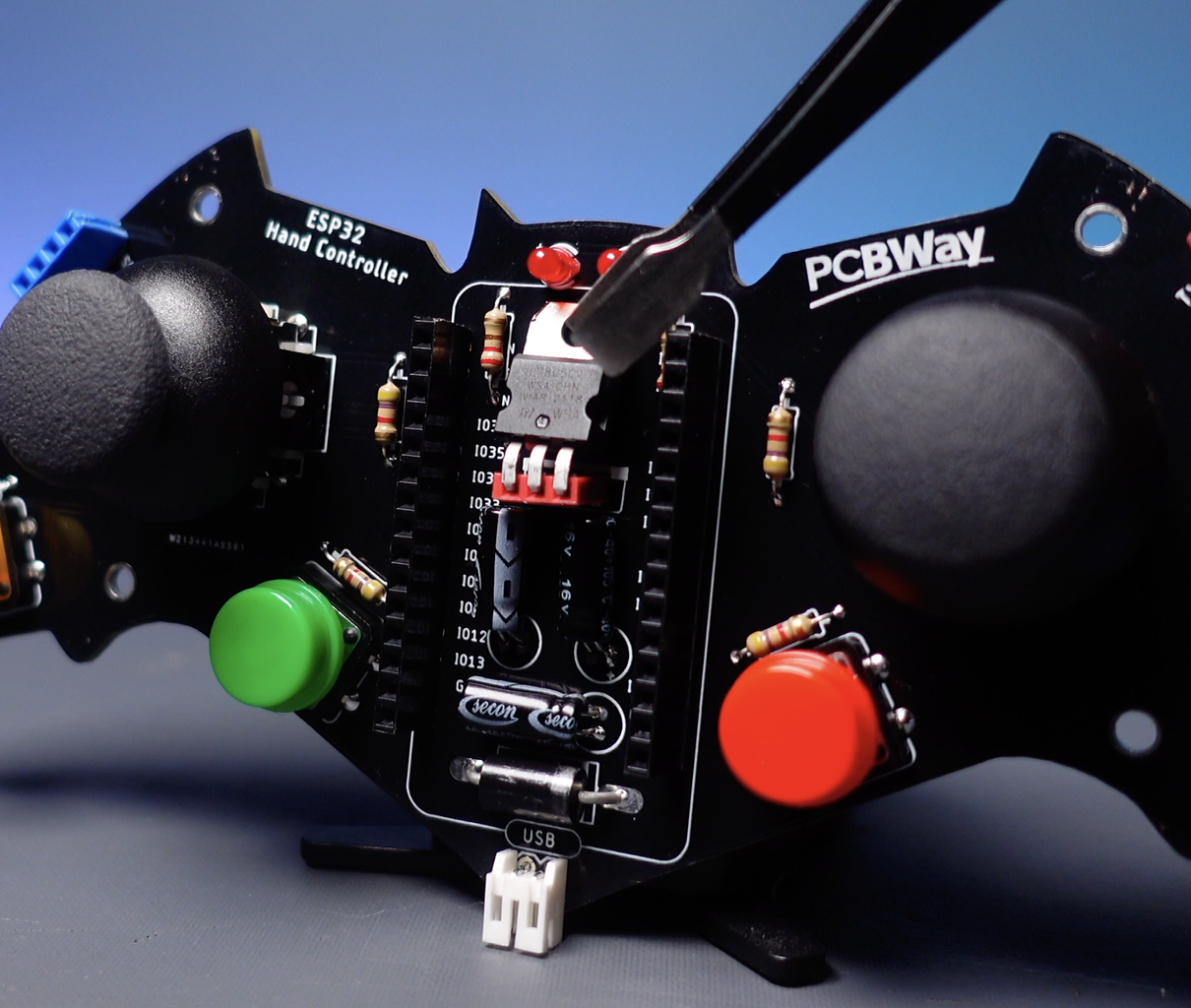
Step 7: Printed Circuit Board


I have a Bat-themed printed circuit board that I designed earlier and I will test it as a GamePad, if it works well I will revise it and design a new version for next use. Printed circuit boards are used to design more durable and stable electronic circuits for long-term use. I prefer PCBWay for printed circuit board service, you can easily upload the GERBER file and place an order quickly. Your order will be delivered in a few days, depending on your location. You can choose PCBWay for high-quality and low-price PCB service.
Just like the breadboard circuit, easy-to-assemble solderable components were preferred. Mount the required components on the PCB and solder them in place with the soldering iron and solder wire.
- 1x Diode SB560
- 3x Capacitor 100uF 16V
- 2x XY Thumb Joystick
- 1x Regulator 7805CV (*Optional)
- 2x LED 3mm
- 2x Resistor 220R
- 6x Resistor 4K7
- 1x Doit ESP32 DevKit V1
- 2x Female Header 1x15 2.54
- 2x Female Header 1x4 2.54
- 1x Connector
- 4x Push Button Switch 12mm With Round Cap
PCB Gerber files - pcbway.com/project/shareproject/DIY_ESP32_Bluetooth_GamePad_for_Android_PlayStation_and_PC
Step 8: Testing the Printed Circuit Board


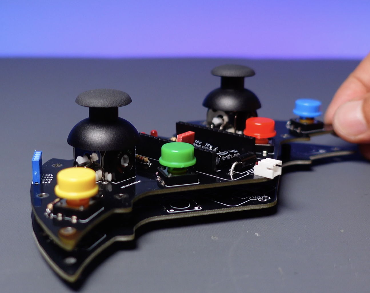


The design includes 4 buttons and 2 joysticks, as well as one button connected to each joystick. Therefore, I will customize the source code for a total of 6 buttons and two joysticks.
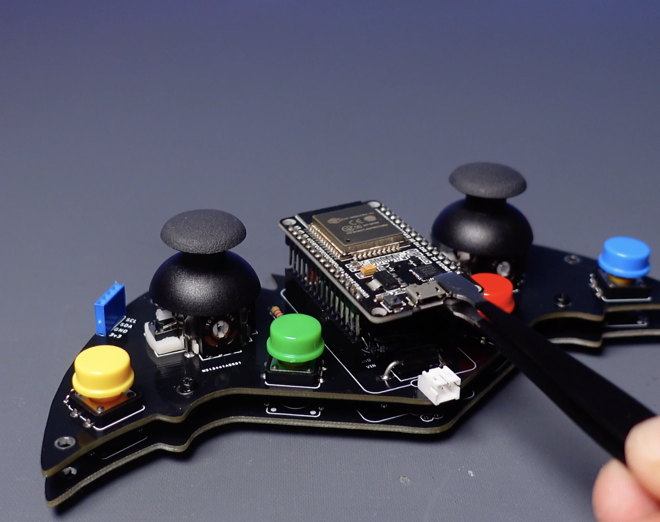
Then I upload the source code. The circuit includes a female header for the voltage regulator. If you want to power the circuit with an external power source and the power voltage is higher than the ESP32's operating range of 6 to 12 volts, you should use a regulator (*7805CV).
You can power the circuit from the USB input of the ESP32 without using the regulator, you can also power it through an external supply in the 6 to 12 volts power range using a jumper.
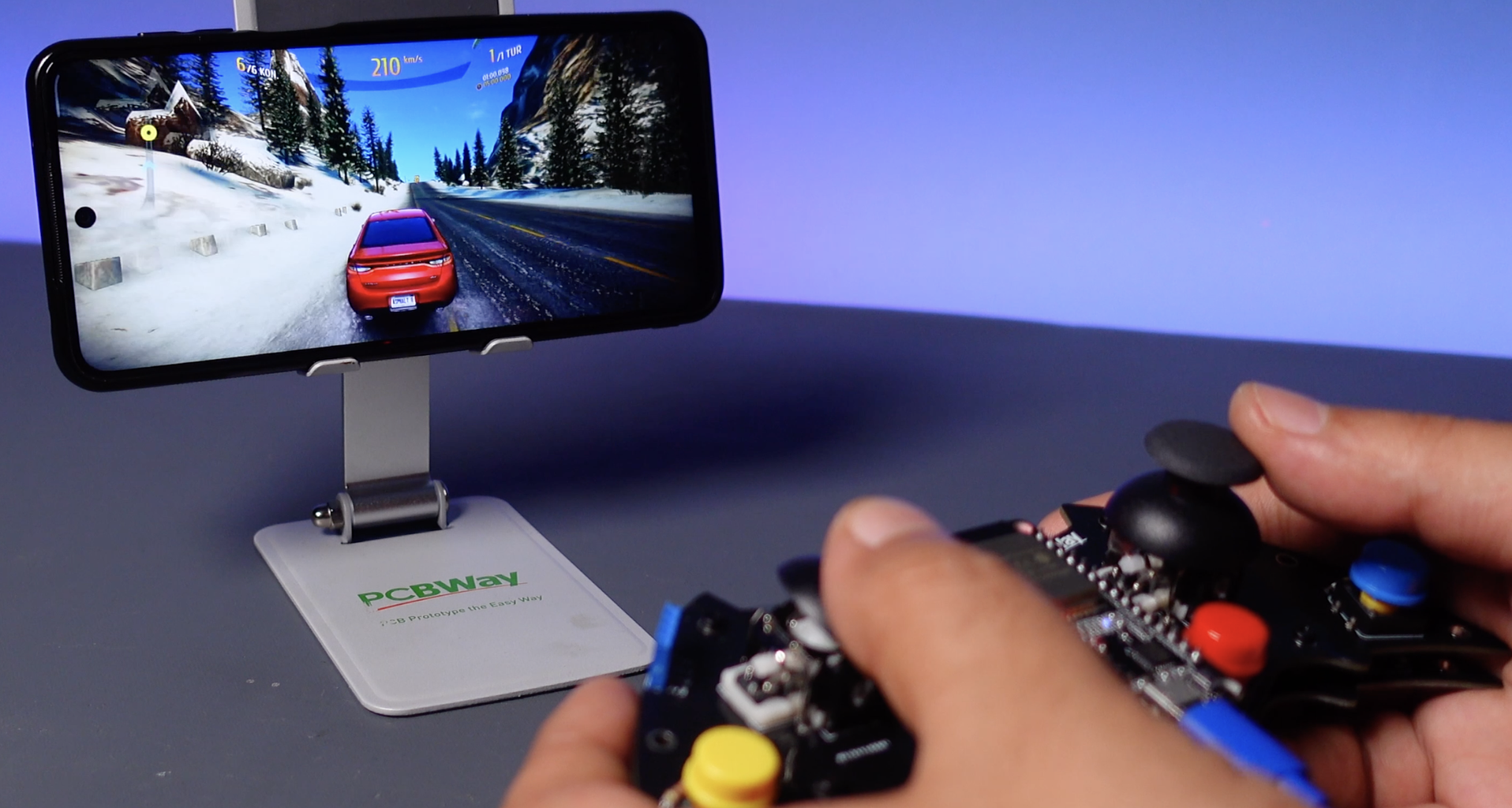
I used one of the blank PCBs as a cover to avoid hand contact with the circuit. I plug the ESP32 board into the circuit, then test the buttons and joysticks via the gamepad tester app. Next, I open the car racing game for control testing.
Attachments
Step 9: Conclusion and Recommendations


The circuit works great on Android-based smartphones as seen in the video. Also, I tested it on Android TV and Android TV Box again with great results. Testing was still successful on a Windows-based PC, but I had some glitches with the connection on my MacBook. As a result of my research, I assigned PS mode to the Joystick button and kept it pressed while establishing a Bluetooth connection, the connection was successful and the MacBook recognized the circuit as a game controller. I also tested the circuit with two ESP32s to communicate with each other using ESP-NOW, and the result was successful.
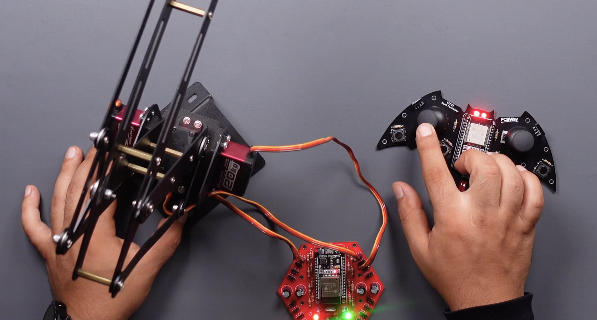
If you ask what else I can do with this circuit, here are a few sample projects... You can use this PCB in your projects with many wireless communication options such as ESP32 to ESP32, and Bluetooth to WiFi.
- https://www.instructables.com/ESP32-Joystick-Hand-Controller-ESP-NOW/
- https://www.instructables.com/ESP32-Servo-Motor-Controller-Board-Wireless-Contro/
- https://www.instructables.com/ESP32-Mecanum-Wheels-Robot-and-Bluetooth-Gamepad-C/
Thanks for reading the project article. You can send your questions in the comment section, I will try to answer them when I have time.


