

Introduction: DIY Infrared Sensor Module


Have you ever wanted to make a line following robot but the infrared sensors were too expensive for you? Do you want to upgrade the robot in my other instructable?
Well this instructable comes in two stages, Stage 1 is the prototyping stage, where you build the circuit on the bread board and debug it for design flaws.
Stage 2 is fabrication where I’ll teach you how to create a strip board product that you can plug straight into your robot.
The good thing about this tutorial is you’re able to do many things with these sensors.
Also, if you’re from the UK and have a maplin store near you, you’ll be able to get some IR transmitter and receivers for 99p (They’re side facing LED/phototransistors, so you can have a low-profile sensor module), More on this at the end of the instructable.
1x Arduino
1x Bread board
1x Strip board
1x Wire reel, black
1x Wire reel, red
1x Wire reel, green
2x Infrared LED (Maplin/Sparkfun)
2x Phototransistor (Maplin/Sparkfun)
2x Red 5mm LED (Maplin/Sparkfun)
2x 1k Ohm resistor
2x 220 Ohm resistor
Wire cutters
Wire strippers
Helping Hands
Heat shrink tube (Not used)
Heat source (Not used)
Soldering iron
Solder
Step 1: Let's Get Started


You want to take your bread board and your infra red LED’s and photo transistors and place them side by side (1 hole apart) in the bread board, repeat for the other infra red pair.
Now let’s start wiring up the infrared LED’s first, place a 220 Ohm resister in the same row as the IR LED cathode then wire it to ground, and make sure to wire both. Next you need to wire up both of the IR LED anodes to the power rail.
Step 2: Keep Going


Now we’re moving onto the photo transistors. Take the red LED’s and place the cathode in the photo transistors anode row, next we place a 1k Ohm resistor inside the photo transistors cathode.
Now we take a wire and connect the anode of the red LED to the power rail. We also need to ground the photo transistors do that now.
Now we just need to wire the photo transistors to the analogue inputs zero and one, to do this wire the cathode of the photo transistor before it goes to the 1k Ohm resistor, the left most wire should go to analogue zero and the one on the right should go to analogue one.
Step 3: It's Alive, Alive!!!


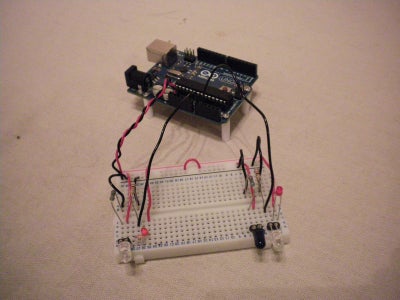
Now if you wire in the power supply from the Arduino (+5v and Ground) if you wave your hand in front of the IR LED/phototransistor pairs, you should notice the red LED’s fading from dim to bright and back as you move your hand. If the LED’s are indeed facing back and forth congratulations you’ve completed the basic prototype, you can move onto the next step.
How ever, if you’re not getting any results from waving your hand back and forth you must check your wiring (Maybe your IR LED’s are either burned out or put it in backwards).
Step 4: The Code


If you want to test out the circuit, upload the following sketch to your Arduino.
/* Line Following RobotOnce you've uploaded the sketch to your Arduino open up the serial monitor and you should notice a series of values been printed in the window e.g. “Left = 21 – Minor Correction”.
Demonstrates the use of IR LED's for a simple line
following robot, if it leaves the black line it will
attempt to locate it.
The circuit:
* Follow the instructable on how to construct it.
created 2011
by Dominion-Network
This example code is in the public domain.
*/
// Motor Outputs
// Left Motor
int M1B = 11; // Reverse
int M1F = 10; // Forward
// Right Motor
int M2B = 6; // Reverse
int M2F = 5; // Forward
// Motor Speed
int mSpeed = 115;
// 2 IR Sensor Analog Input Pins
int LIRPin = A0; // Left Sensor
int RIRPin = A1; // Right Sensor
// 2 IR Analog Reading variables
int LIRReading; // Left Reading
int RIRReading; // Right Reading
void setup(void) {
Serial.begin(9600); // For debugging purposes
pinMode(M1F, OUTPUT); // Motor 1 Forward
pinMode(M1B, OUTPUT); // Motor 1 Reverse
pinMode(M2F, OUTPUT); // Motor 2 Forward
pinMode(M2B, OUTPUT); // Motor 2 Reverse
}
void loop(void) {
leftirscan();
rightirscan();
delay(1000);
}
void rightirscan() {
RIRReading = analogRead(RIRPin);
Serial.print("Right = ");
Serial.print(RIRReading);
// We'll have a few threshholds, qualitatively determined
if (RIRReading < 20) {
Serial.println(" - No Correction");
analogWrite(M2F, 0);
} else if (RIRReading < 200) {
Serial.println(" - Minor Correction");
analogWrite(M2F, mSpeed + 10);
} else if (RIRReading < 500) {
Serial.println(" - Moderate Correction");
analogWrite(M2F, mSpeed + 50);
} else if (RIRReading < 800) {
Serial.println(" - Severe Correction");
analogWrite(M2F, mSpeed + 100);
} else {
Serial.println(" - Extreme Correction");
analogWrite(M2F, 255);
}
}
void leftirscan() {
LIRReading = analogRead(LIRPin);
Serial.print("Left = ");
Serial.print(LIRReading);
// We'll have a few threshholds, qualitatively determined
if (LIRReading < 20) {
Serial.println(" - No Correction");
analogWrite(M1F, 0);
} else if (LIRReading < 200) {
Serial.println(" - Minor Correction");
analogWrite(M1F, mSpeed + 10);
} else if (LIRReading < 500) {
Serial.println(" - Moderate Correction");
analogWrite(M1F, mSpeed + 50);
} else if (LIRReading < 800) {
Serial.println(" - Severe Correction");
analogWrite(M1F, mSpeed + 100);
} else {
Serial.println(" - Extreme Correction");
analogWrite(M1F, 255);
}
}
That means the left sensor is getting more light reflected into the photo transistor and will correct it's course to reduce the light been reflected by turning either left or right until the value has been decreased below the threshold.
Here's a simple concept demo.
Step 5: Optional Step 1
This is an optional step, if you’ve got any heat shrink tubing slip it over the photo transistors and heat it up until its snug, make sure to trim the end of the tubing so the tip of the photo transistor is poking out.
This will help block out most if not all the ambient light to improve the readings.
Step 6: Placing the Componants


Now we move onto the good stuff, the strip board fabrication.
Take your strip board and mark an area that is about five by nine holes long then snip the rectangle out.
Take your components one by one from your bread board and recreate the circuit on the strip board the same way you created the bread board prototype, start with the IR LED’s and photo transistors.
Bend the components legs slightly to keep them on the strip board.
Step 7: Soldering


Once you’ve finished placing all the components on the strip board cut four lengths of different coloured wire (1x red, 2x black and 1x green, yellow or white respectfully), again bend the wire slightly so it holds in place on the strip board.
I apologise for this step as I forgot to place a ground wire from the 1k Ohm resistor to the empty hole between the 220 Ohm resistor and the other ground wire.
Alternatively, if you’ve got some male header pins like me, cut three off and solder them in place instead of the wires (You will still need the previously mentioned 1k Ohm to 220 Ohm resistor ground wire), This is what I’ve done.
Step 8: End Result and Going Further


This is another optional step, instead of creating separate modules that you can connect via 3 wire connectors, you can make a strip module that uses a 5 pin header, that’d be 3 photo transistors/infra red receivers and 4 IR LED’s/transmitters so the header would look like this.
Another step you could take is by buying some IR transmitters and some IR receivers from Maplin (Can’t find USA Equivalent) they’re side facing so you can bend the legs so the back of them are touching the strip board which means you can have them closer to the ground for more accurate readings.
Here's some suggestions to expand on this instructable.
- An alternative input device (See Make - Arduino Bots and Gadgets: Interactive Painting)
- An extremely basic edge avoiding robot, using the IR sensors, like the line following robot with altered code you’ll be able to tell the robot it has come to an edge and needs to turn around.
- Maze solving robot, like the line following robot, or edge avoiding robot with slight alteration to the code you could have your robot attempting to solve mazes.
- A basis for a motion sensor project (See 51 High-tech Practical Jokes For The Evil Genius)


