

Introduction: DIY WIRELESS REMOTE CONTROLLER FOR ROBOTS, RC BOATS ..


How much essential it is ,to make an efficient wireless remote controller for your projects like robots, RC cars, RC boats etc.. It is the remote controller which effects the whole performance. It is sure that a good remote controller can make your robot well functioning. In this post I am showing how to make a efficient, simple remote controller using an arduino and two joystick modules.
Choosing the wireless transceiver - 'NRF2401'
I choose NRF2401 RF module as the transceiver(transmitter & receiver) because it is a very low cost and very efficient RF modules with a good range.
Watch this video to see it's working with my new robot-
VISIT HERE TO SEE THE TUTORIAL OF THIS ROBOT
Here download all the files (Circuit diagrem and Arduino code)
Attachments

Step 1: Materials Needed.
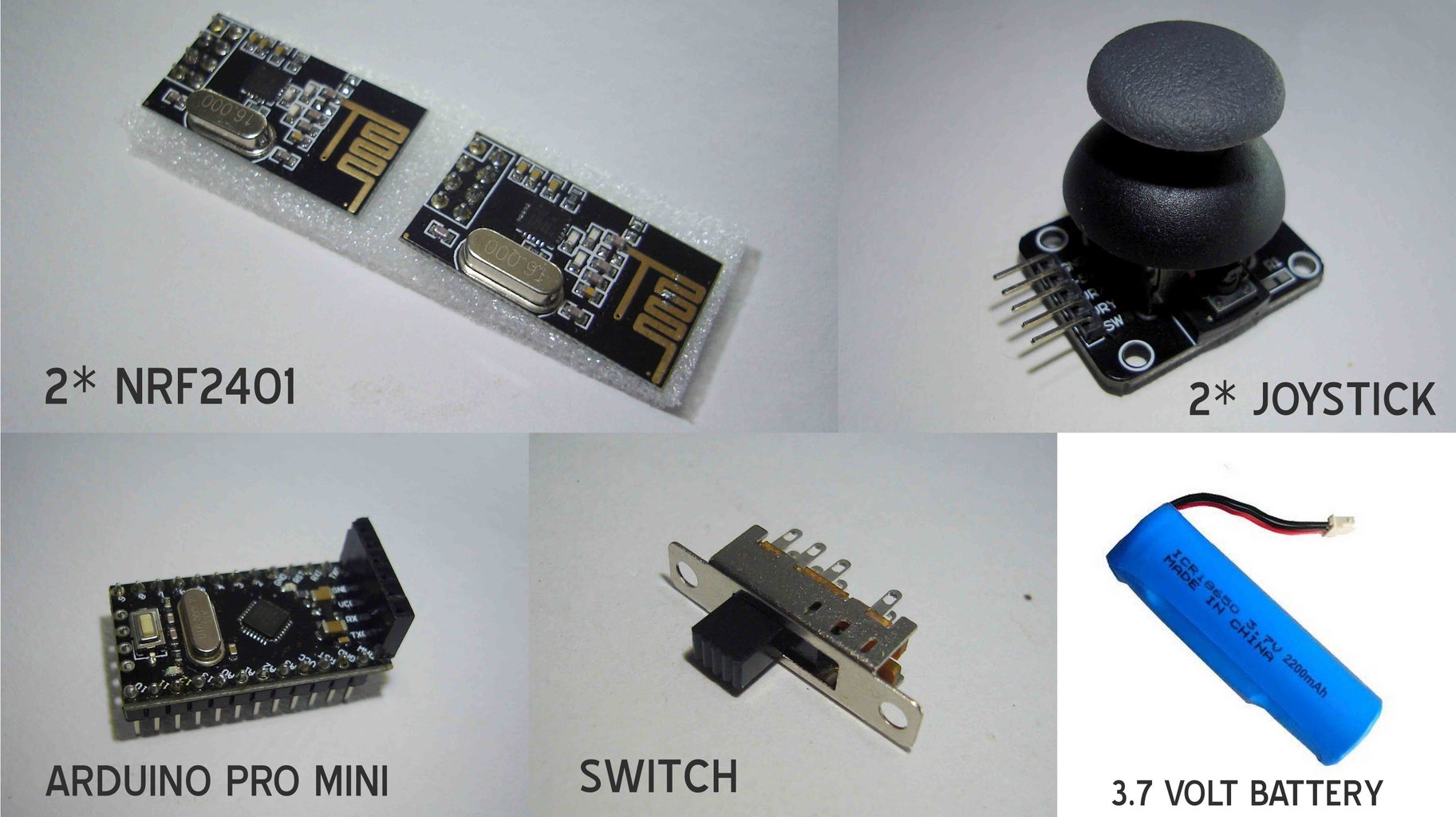

Materials-
- 2 x NRF2401(one for this remote and another receiver) - Amazon.in or Amazon.com
- Arduino Pro Mini - Amzon.in or Amazon.com
- 2 x Joystick modules - Amazon.in or Amazon.com
- Small Switch (from a local electronic shop) or Amazon.com
- 3.7 volt rechargeable battery - mepits.com
Body parts (it's body is from scratch!) -
- 2 x Old cracked Mosquito Killer bat
- Some small plastic pieces
Step 2: Let's Make It Case/body


Cut the part from the bat as shown in the figure and make a square hole in the upper side of the part. Then take a small plastic piece and make a round hole on it for connecting the joystick and then glue the plastic piece to the part . Make one more of this same type .
Step 3: Circuit Diagram and Wiring Instraction


Wiring instruction' NRF2401' >> 'ARDUINO'
- VCC >> VCC
- GND >> GND
- MISO >> PIN 12
- MOSI >> PIN 11
- SCN >> PIN10
- SCK >> PIN 13
- CE >> PIN 9
- IRQ (not in use)
Wiring instruction 'left Joystick module' >> 'ARDUINO'
- VCC >> VCC
- GND >> GND
- VER (Y axis) >> A0
- HOR (X axis) >> A1
Wiring instruction 'right Joystick module' >> 'ARDUINO'
- VCC >> VCC
- GND >> GND
- VER (Y axis) >> A2
- HOR (X axis) >> A3
Wiring instruction of switch
- Middle leg to >> Battery +ve
- Upper leg to >> Charging port +ve
- Down leg to >> Arduino pro mini pin 'RAW'
Battery -ve to >> Arduino pro mini pin 'GND'
Step 4: The Electronic Parts of -


Here we are going to connect the electronic parts to the left side case of the remote.
First glue the arduino to the upper side of the case and take out a wire from it as per the circuit diagram shown in the previous step. Then connect the NRF2401 RF transceiver to the arduino. The switches that I have shown in the figure are not been used in this tutorial there fore I am not going to describe it. Then connect the Joystick module and take out the knob of the joystick through the round hole. Connect a 3 terminal switch (on-of-on) also to the same.Now we finished the electronic section of the left case of the remote. Also take out the wires for the joystick and battery which is to be connected to the right side case of the remote.
Step 5: Finishing the Left Side Case.


Parts
- 2 x Long bolt
- 6 x nuts
- A small kural(made fro old pen)
Now make three holes on the left case as shown in the figure for connecting 2 bolts and for taking out the wire from the arduino to the joystick and to the battery.Then screw the bolts and take the wires outside through the hollow tube tube can be anything hollow,a pen body is used here . Now we have completed the left case works.
Step 6: Making the Right Side Case and Connecting Them Together.


Now take the right case .Then make 3 hole on the right case at the same position as the left case. Then connect the battery, charging port and the second joystick module to the case and connect the wires as shown in the circuit diagram. At last connect the two cases together as shown in the figure and close the cases and screw it. In the last image you can see that I have connected a potentiometer ,which is not used now in this tutorial (code of the arduino), If you want to use it then comment me about it.
Step 7: Arduino Code, Finishing Everything and Making It Good Look:)


In this step I have used a thin aluminium sheet to cover the center part of the remote and also added some stickers to make it look better . Now it's work is complete. Here you can find the arduino program needed for the remote, the code that I have provided here is that one I used to control this robot. For the receiver code you can visit that tutorial also. Click here to visit that tutorial.
In this arduino code there is a library called print.h. For using this library in the arduino code you need to add the print.h file and arduino code in a same folder that I have provided below.
If you have any doubts or suggestions please comment below!
Attachments

Participated in the
Arduino Contest 2016

Participated in the
Epilog Contest 8

![Tim's Mechanical Spider Leg [LU9685-20CU]](https://content.instructables.com/FFB/5R4I/LVKZ6G6R/FFB5R4ILVKZ6G6R.png?auto=webp&crop=1.2%3A1&frame=1&width=306)


