

Introduction: DIY Wireless Power Meter | 100VDC 100A


Hey! everyone, My name is Steve
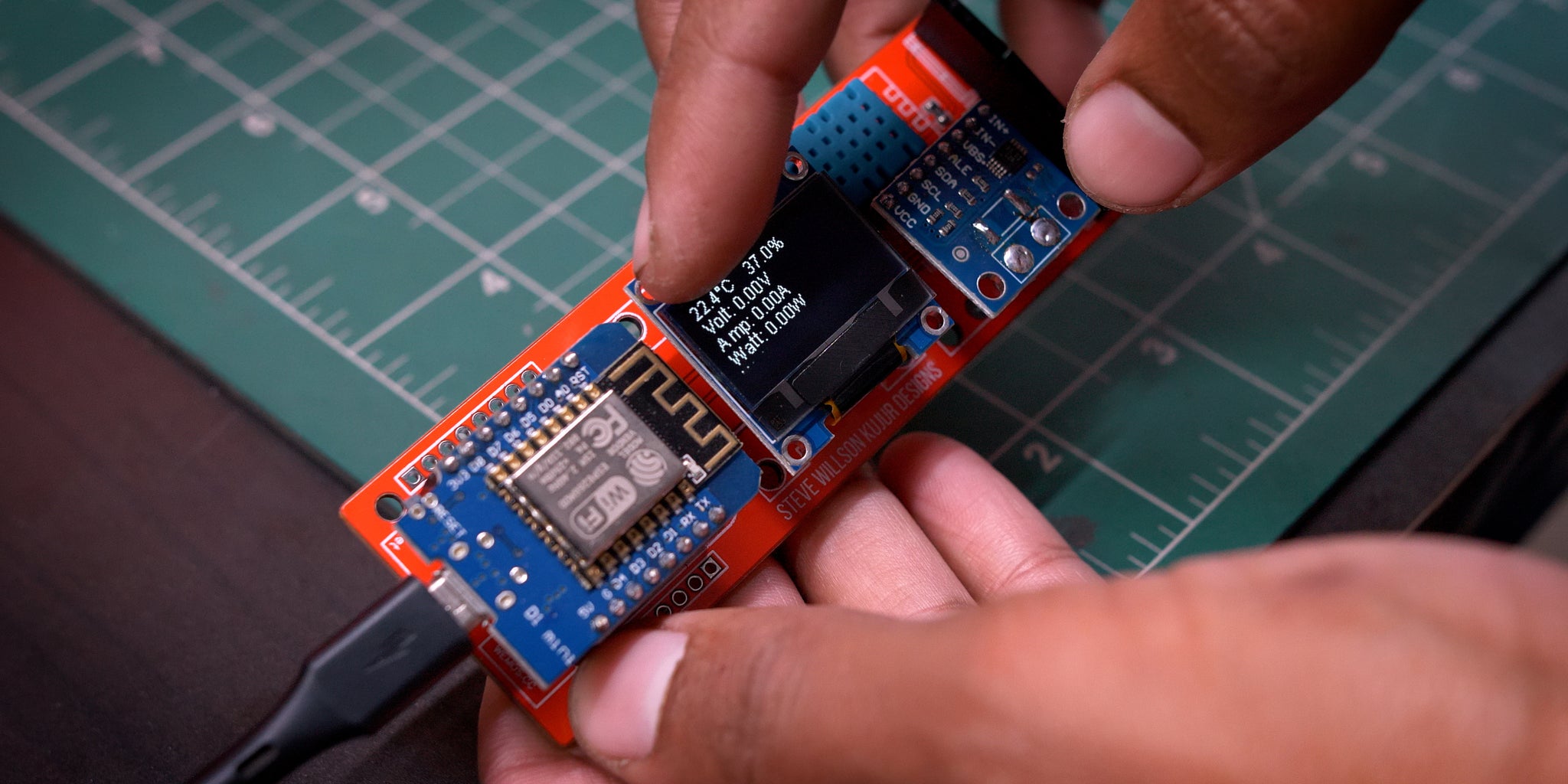
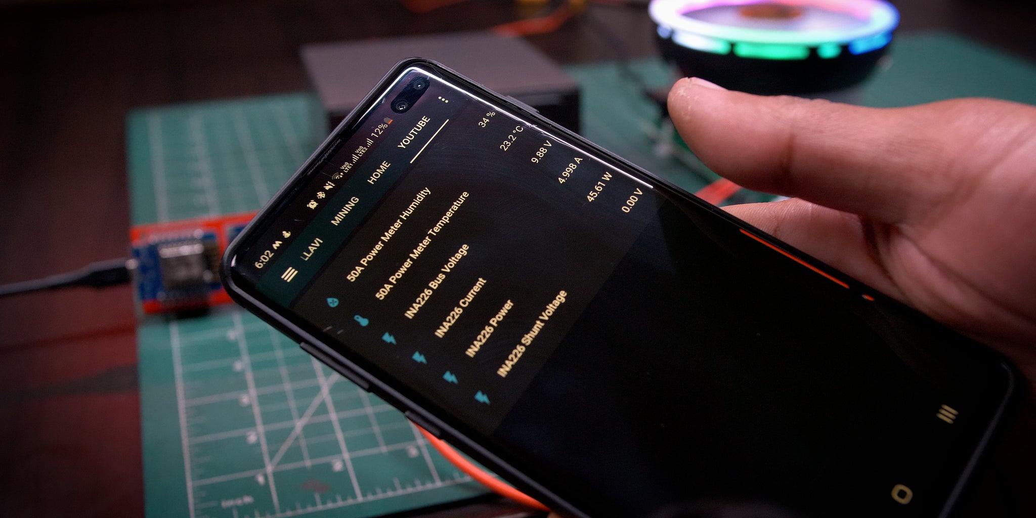
Today I’m gonna show how I build this Power Meter Using ESP8266 & INA226 Current Sensor
The Screen seems to fluctuate it’s just due to the camera in real it’s normal
I’ve built the Codes with ESPHome
These can measure current 1mA to 100Amp and Voltage up to 100VDC, and it’s very precise
And yes it can also measure negative current
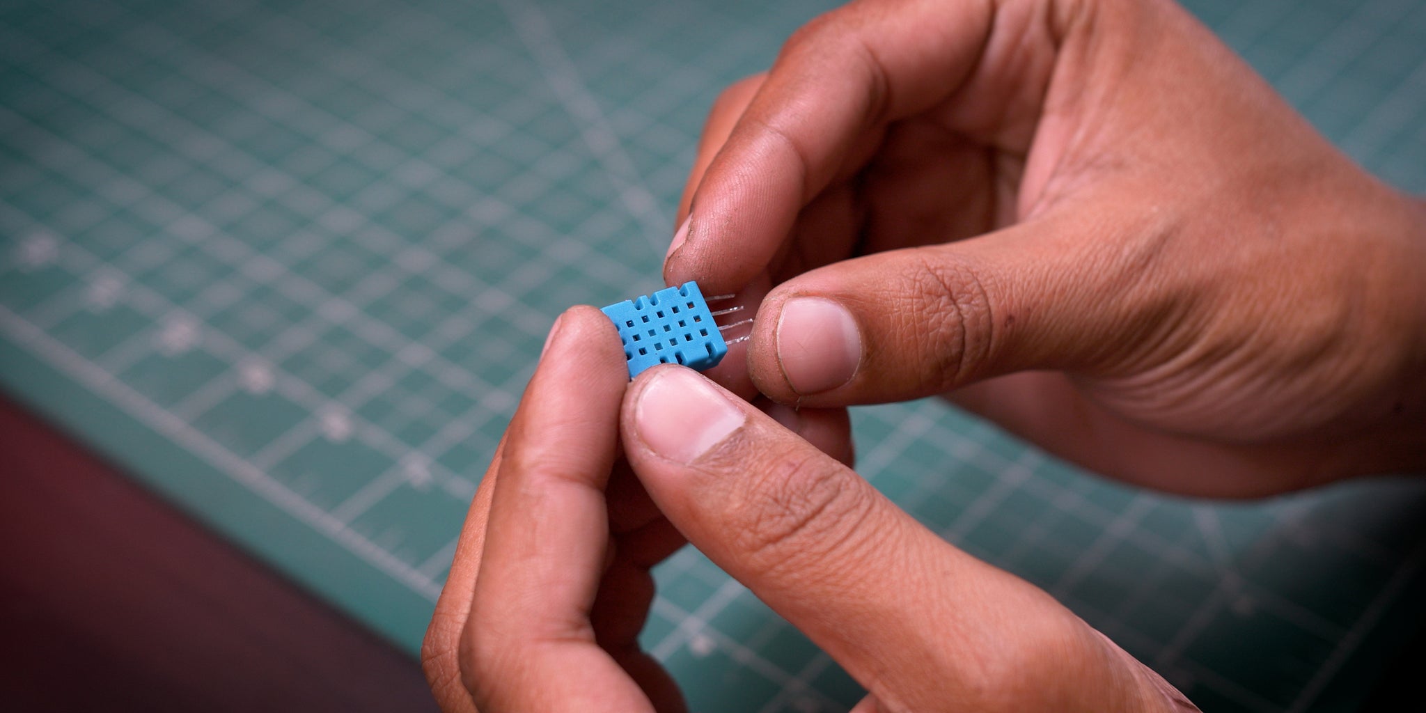
And I also have added DHT11 So it can measure Temperature & Humidity
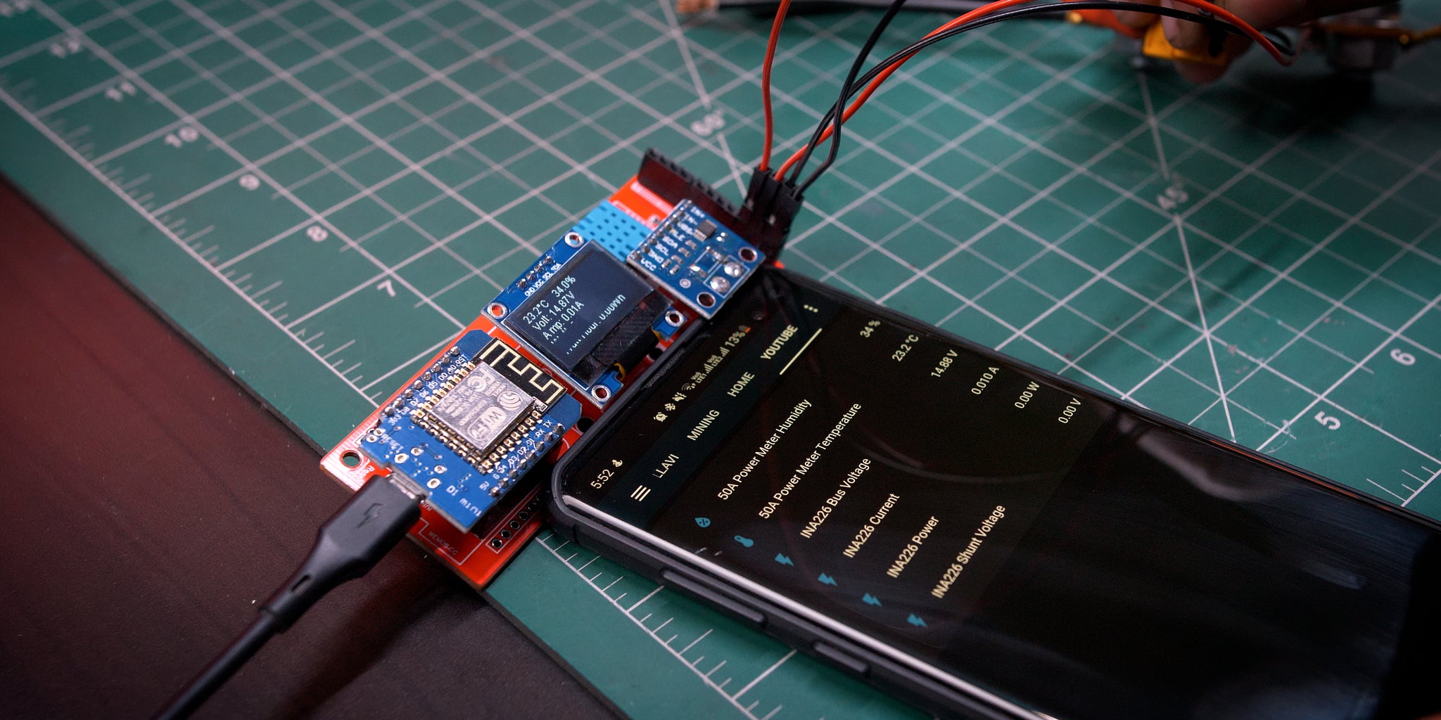
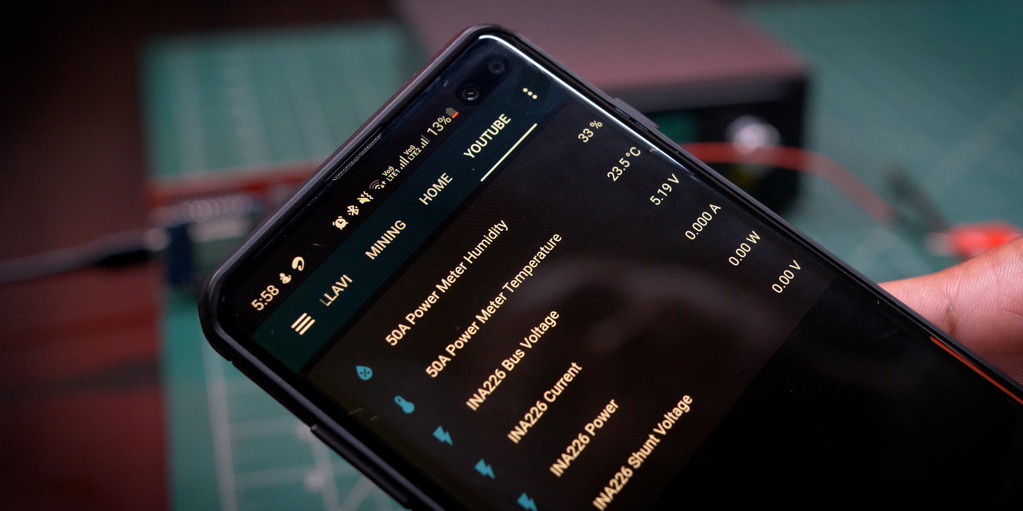
It can also be integrated with your Home Assistant and you can see it wirelessly I’ll mostly use this for capacity testing Lifepo4 Battery
This is the First Version I’ve made there are so many things to improve
Let's Start
Step 1: Features


Input Power
- 5V DC
Measurement
- 0-100VDC
- 0-100A
Built-in Features
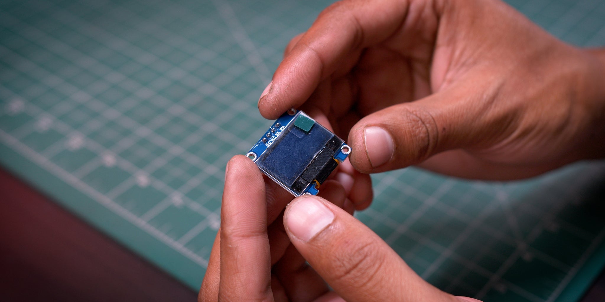
- 0.96" Oled
- OTA Update
- Temperature & Humidity Read
- Wireless
- Extra Ports for Future Expandability
Step 2: Precesion Samples
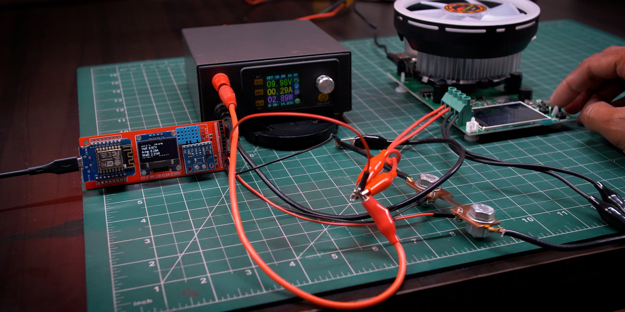


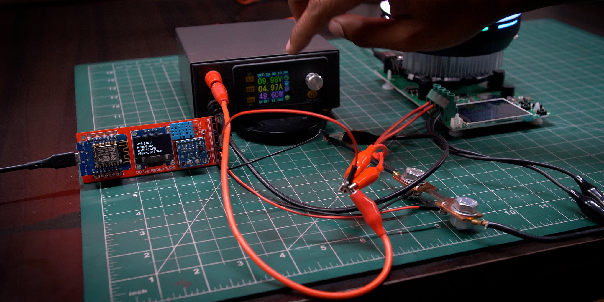

I used my lab bench power supply to test it and it seems very accurate there are very few errors and you can always calibrate it
Step 3: Thing I've Used

Aliexpress
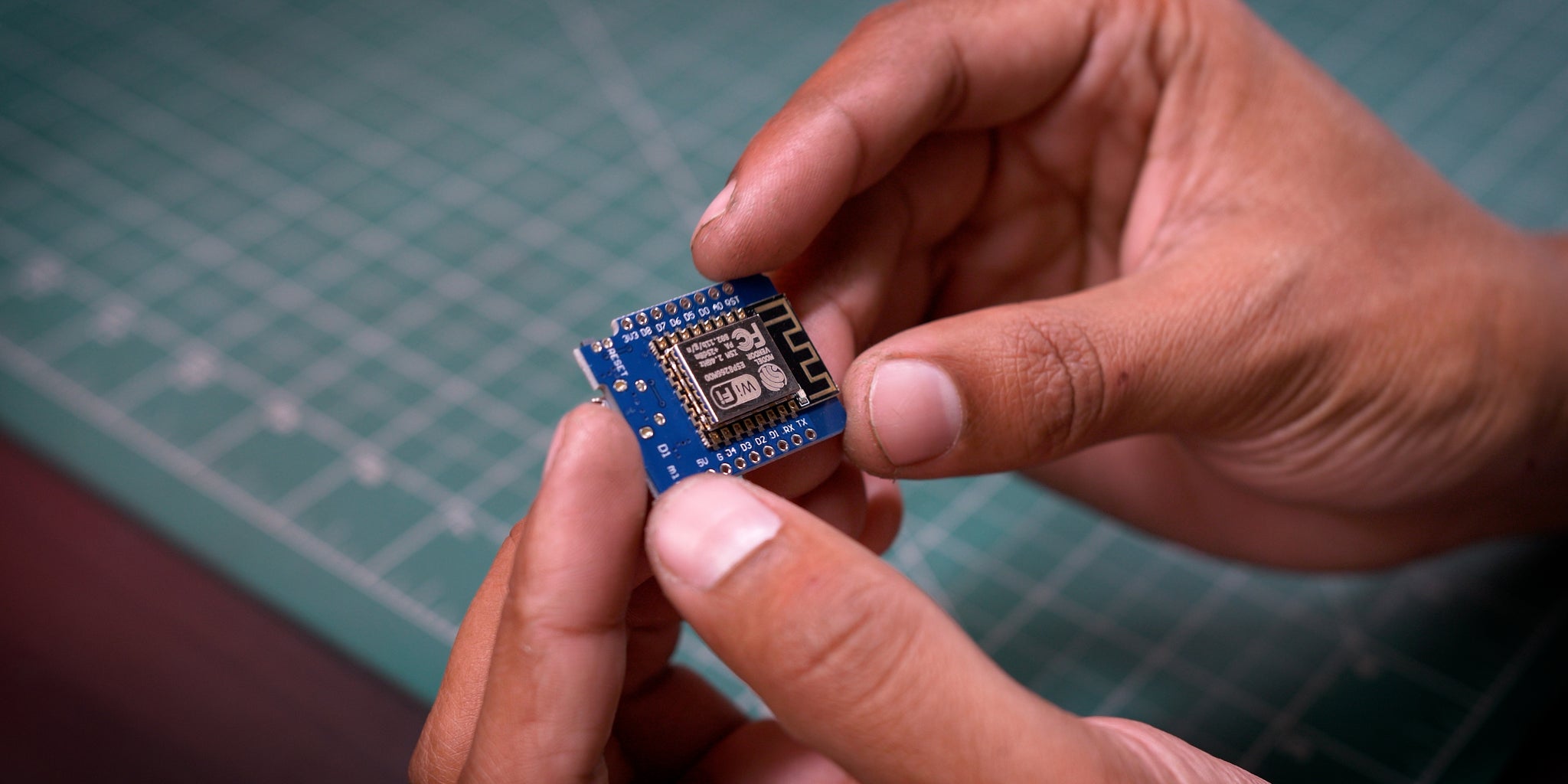
- Wemos D1 Mini - http://bit.ly/37x3Jie
- INA226 Current Sensor - http://bit.ly/3k2OUZO
- DHT11 - http://bit.ly/3k2OUZO
- 0.96 Inch Oled Display - http://bit.ly/3k2OUZO
- SMD Resistance - http://bit.ly/3k2OUZO
- SMD Capacitors - http://bit.ly/3k2OUZO
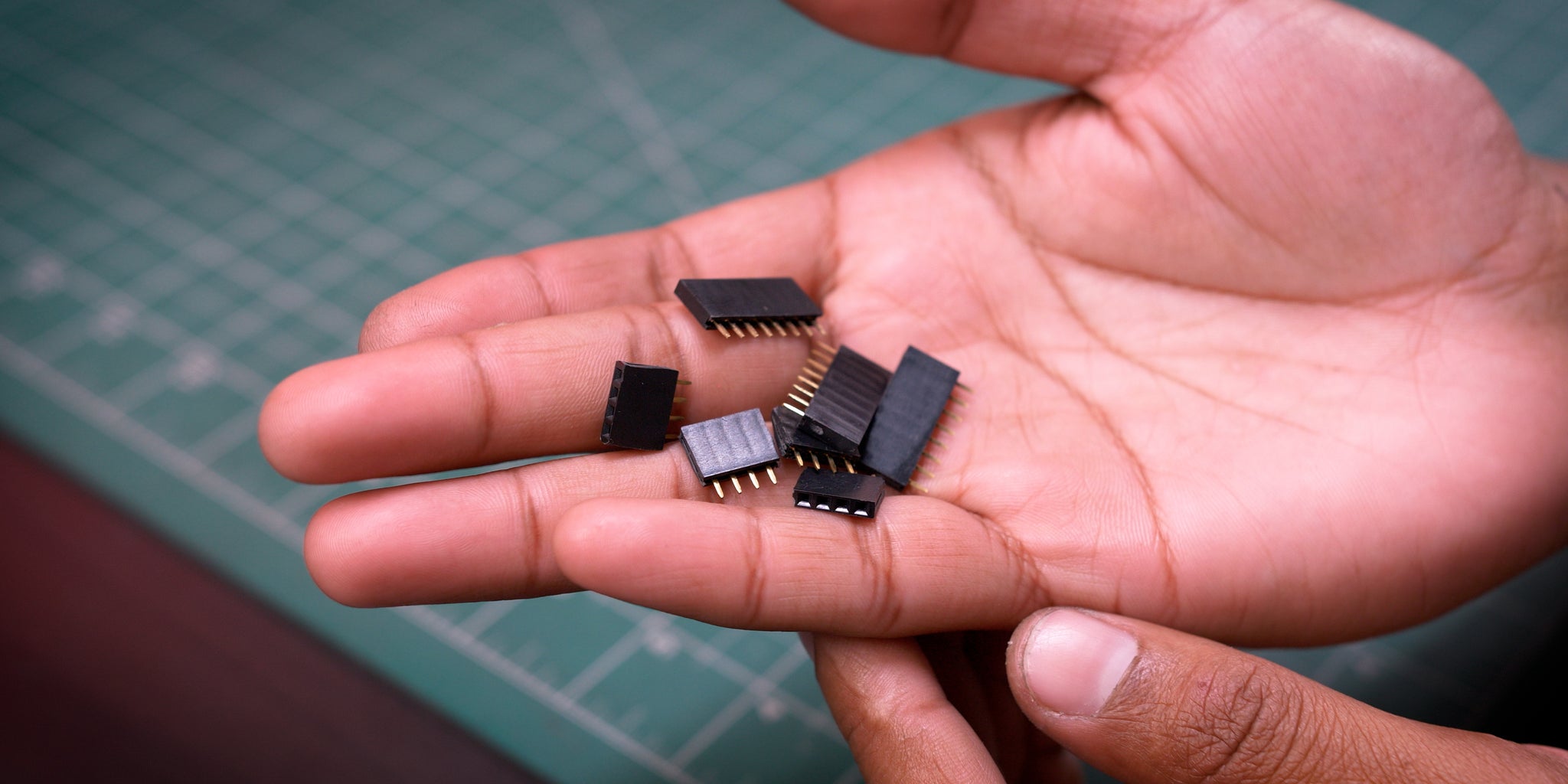
- Female Headers - http://bit.ly/3k2OUZO
- 100A Shunt - http://bit.ly/3k2OUZO
- Load Tester - http://bit.ly/3k2OUZO
- TS100 Soldering Iron - http://bit.ly/3k2OUZO
- Wemos D1 Mini - http://bit.ly/3k2OUZO
- INA226 Current Sensor - http://bit.ly/3k2OUZO
- DHT11 - http://bit.ly/3k2OUZO
- 0.96 Inch Oled Display - http://bit.ly/3k2OUZO
- SMD Resistance - http://bit.ly/3k2OUZO
- SMD Capacitors - http://bit.ly/3k2OUZO
- Female Headers - http://bit.ly/3k2OUZO
- 100A Shunt - http://bit.ly/3k2OUZO
- Load Tester - http://bit.ly/3k2OUZO
- TS100 Soldering Iron - http://bit.ly/3k2OUZO
Step 4: Making PCB


I generally try to make everything professionally so I use JLCPCB to make my dream come true.
Talking about JLCPCB it's the world largest PCB manufacturing company and provide very fantastic results
You can see the above image as a reference
Now, JLCPCB are offering
- $2 for 2Layer, 5pcs
- $5 for 4Layer, 5pcs
Gerber & Schmitics - Download
Step 5: Why ESPHome

I use Home Assistant to run ESPHOME it's very easy to work with and gives wireless capabilities
It uses YAML and the coding is very user friendly
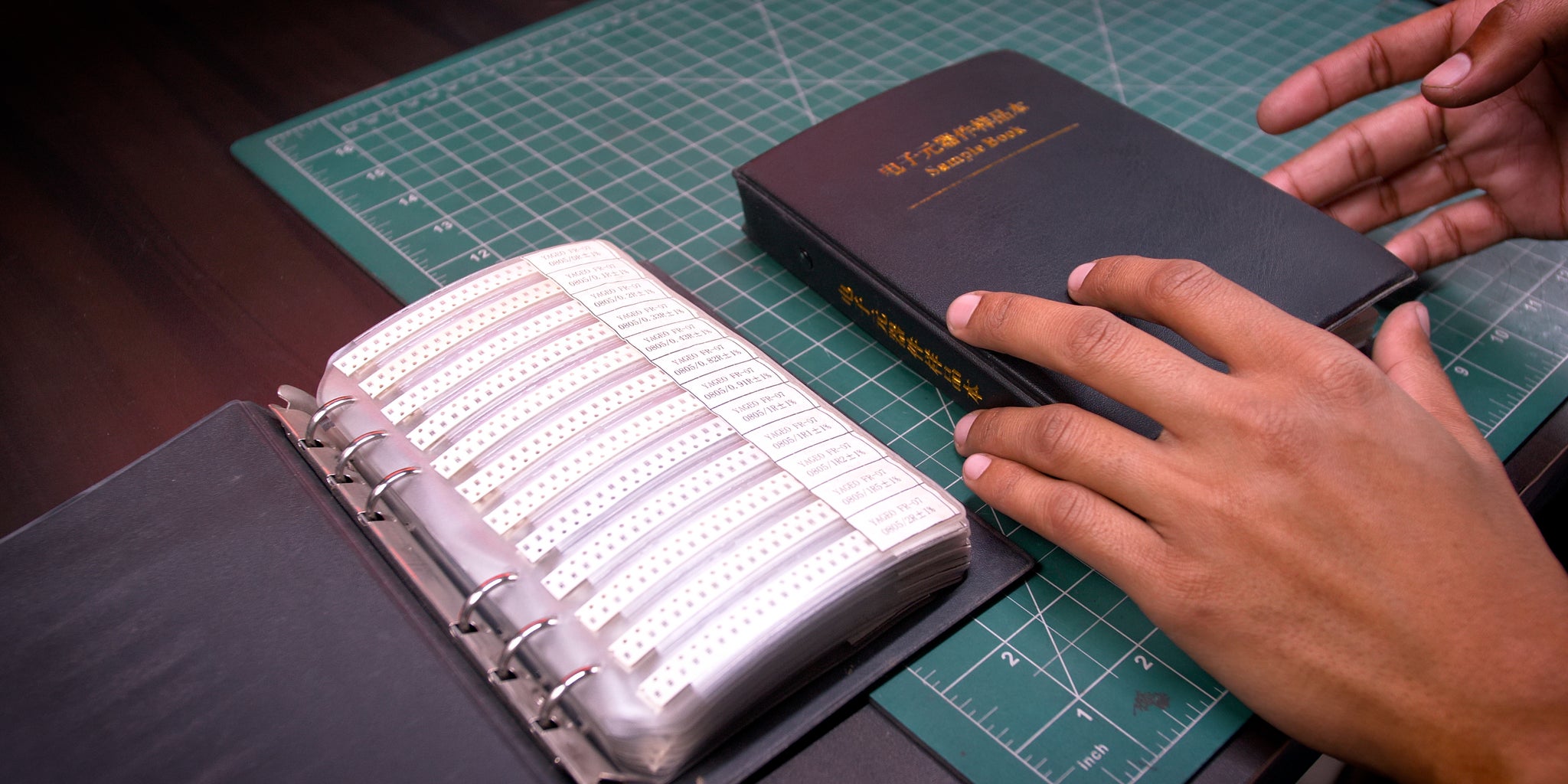
Step 6: SMD

I generally use SMD Resistance and Capacitors Book it's easy to work with everything is well sorted
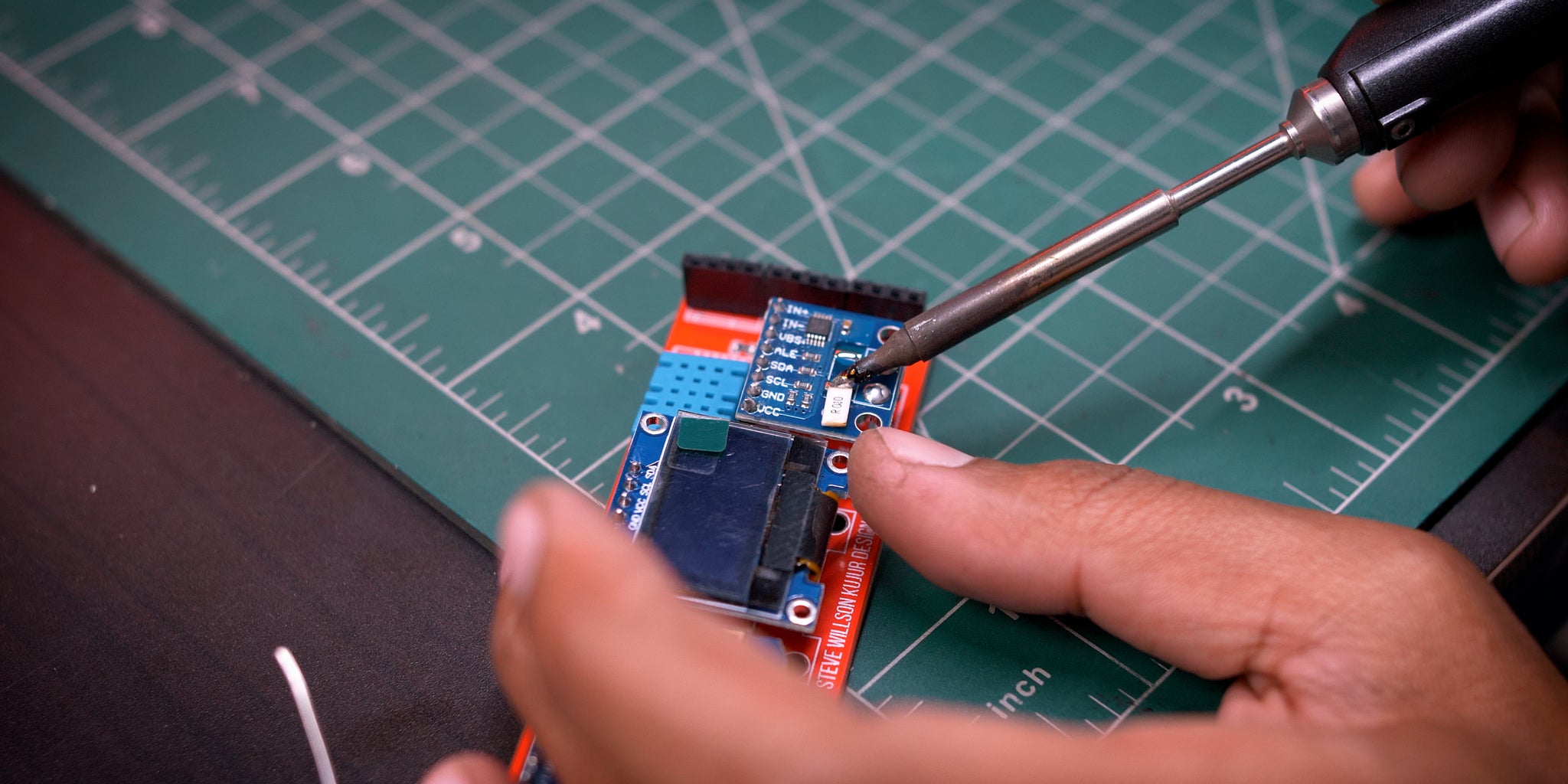
Step 7: After Gathering All the Parts
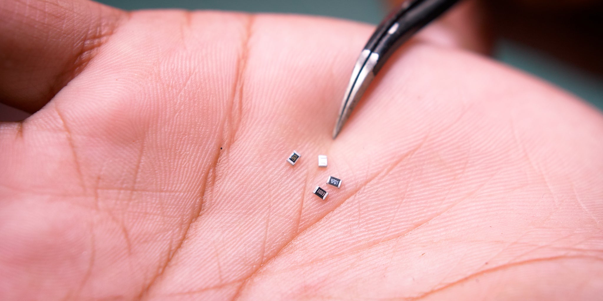


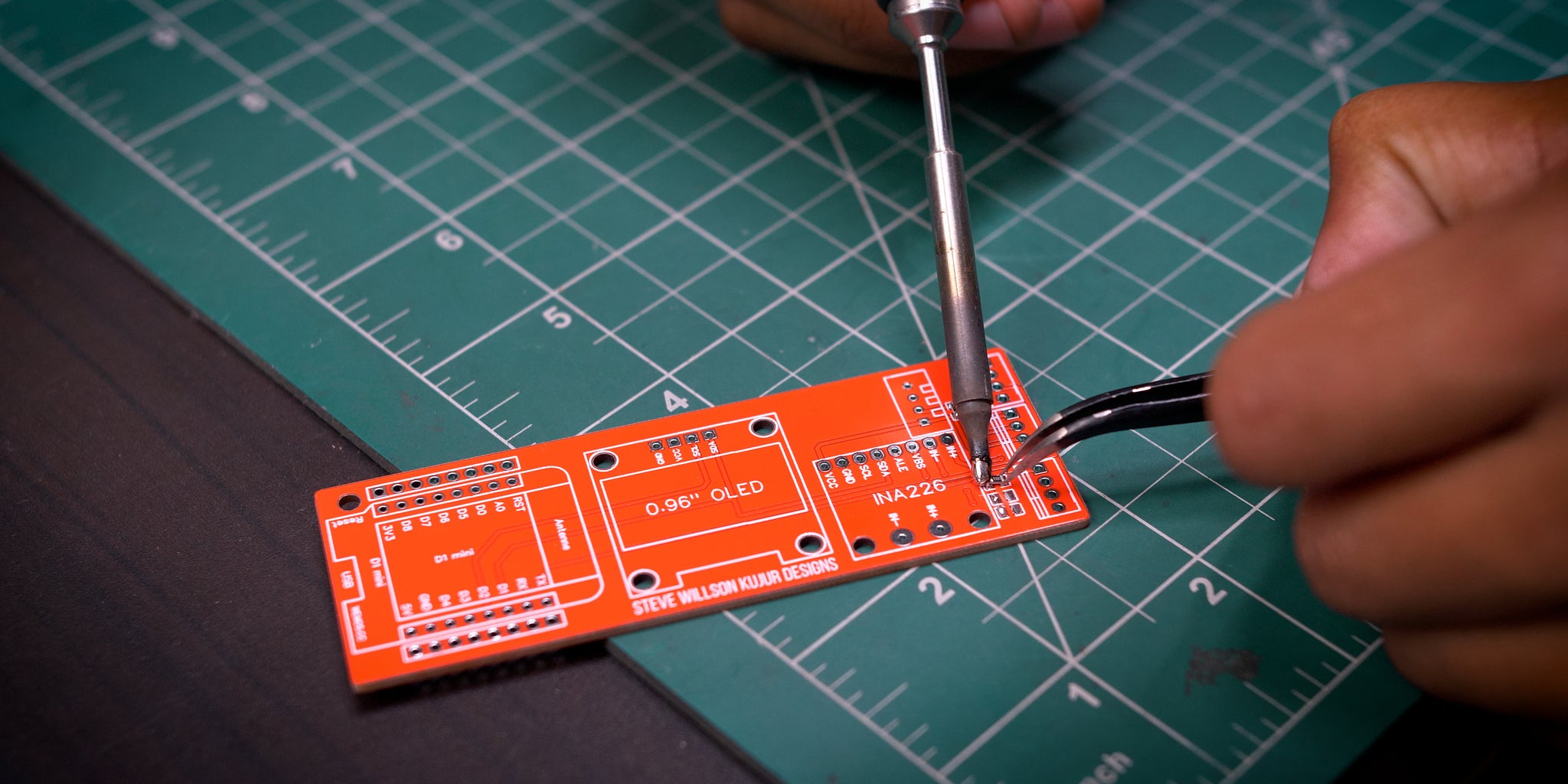


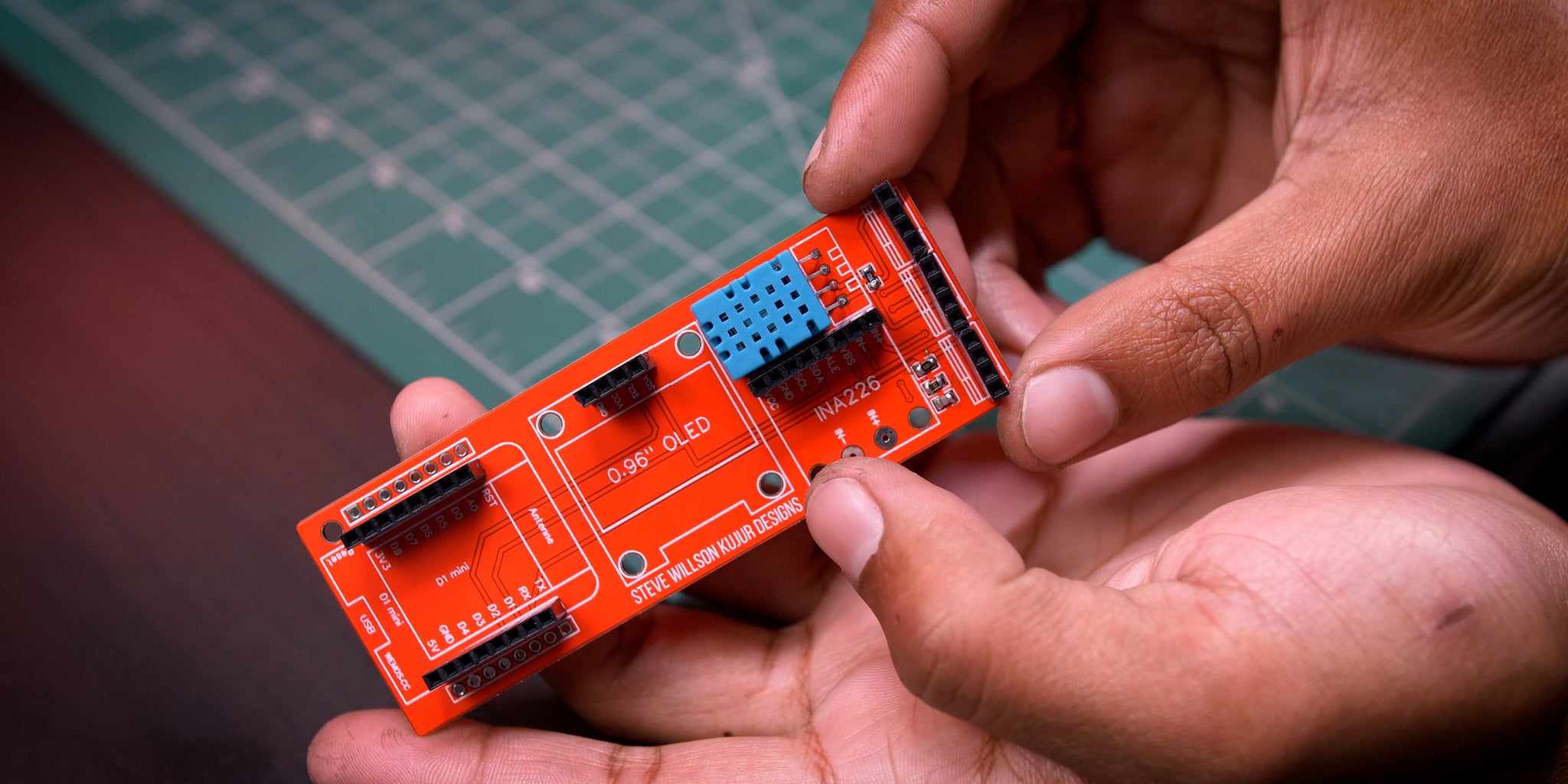
Started Soldering 4 Resistance and 1 Capacitor.
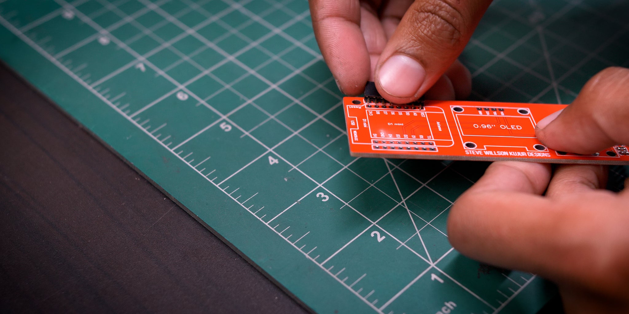
Then soldered the female headers yes it gives height but gives easy replaceability
And soldered DHT11
Note - Please see the images for better understanding
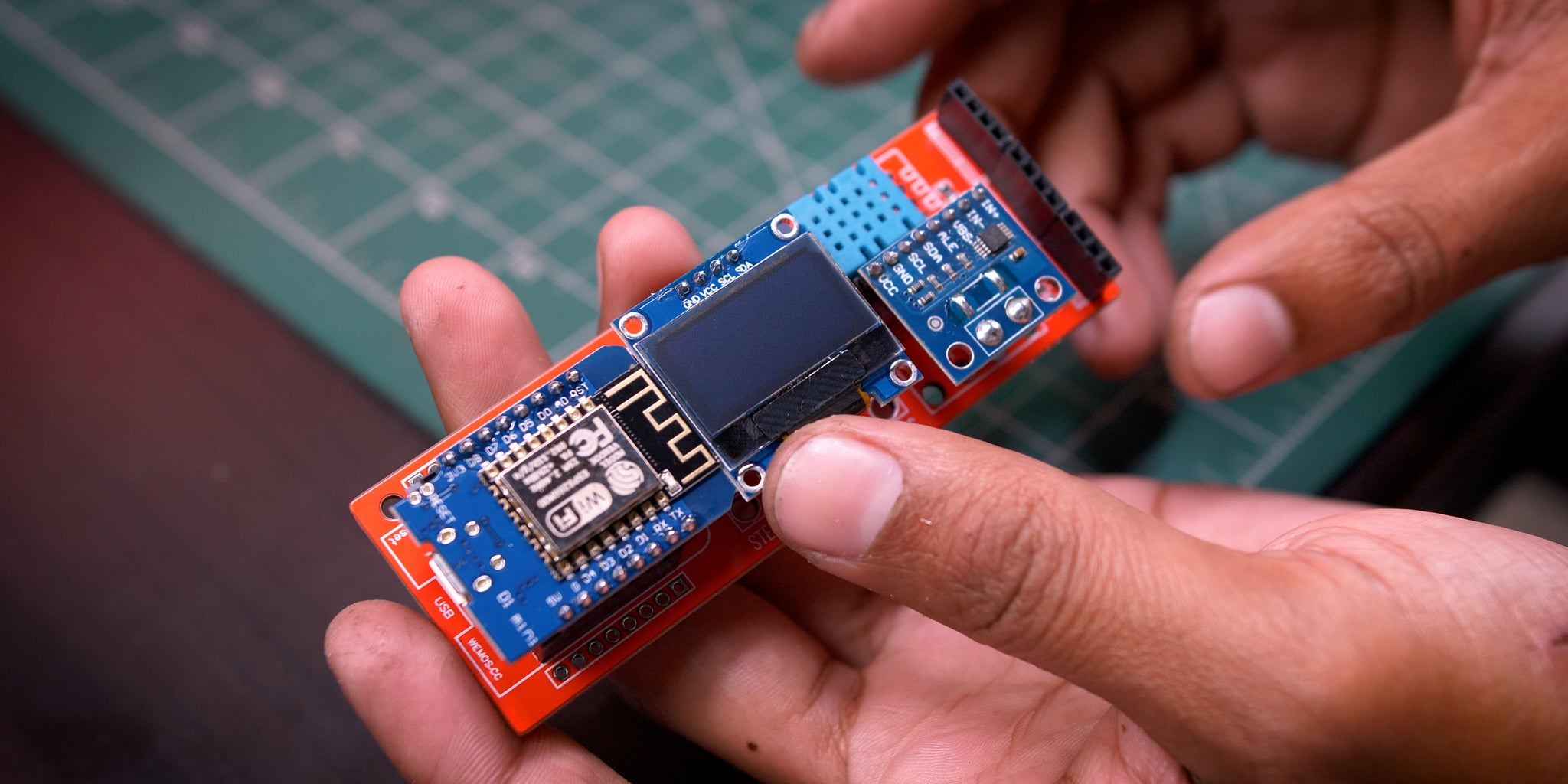
Step 8: Assembly
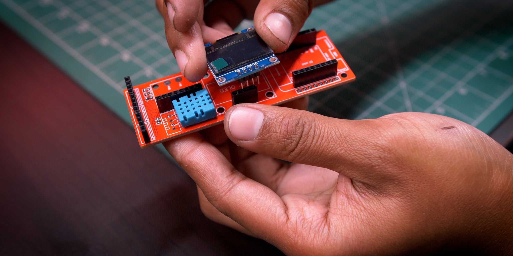
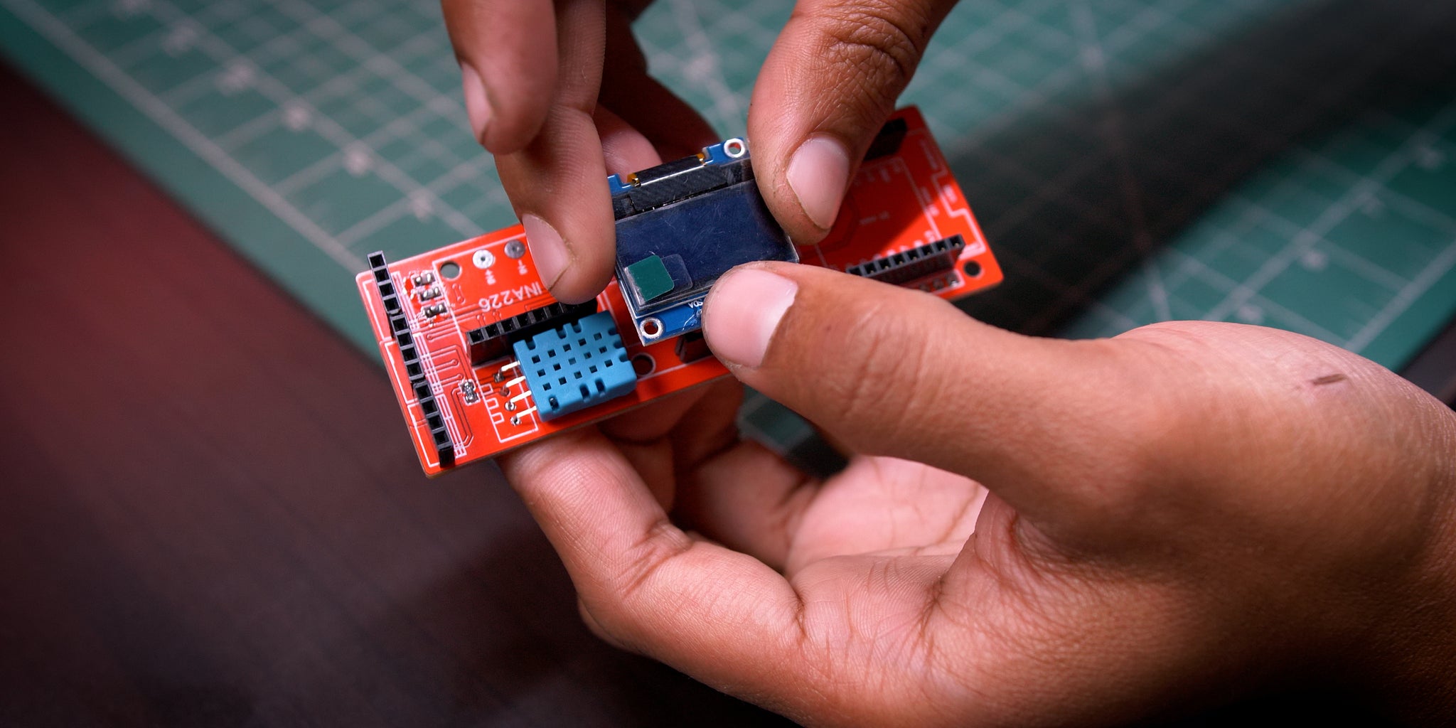
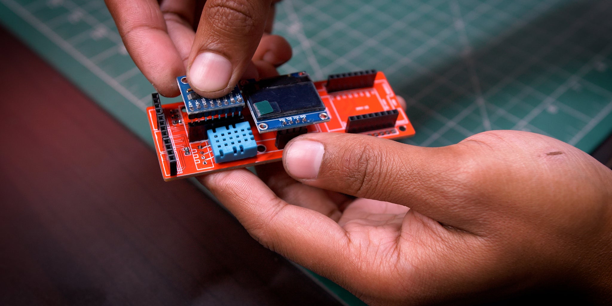
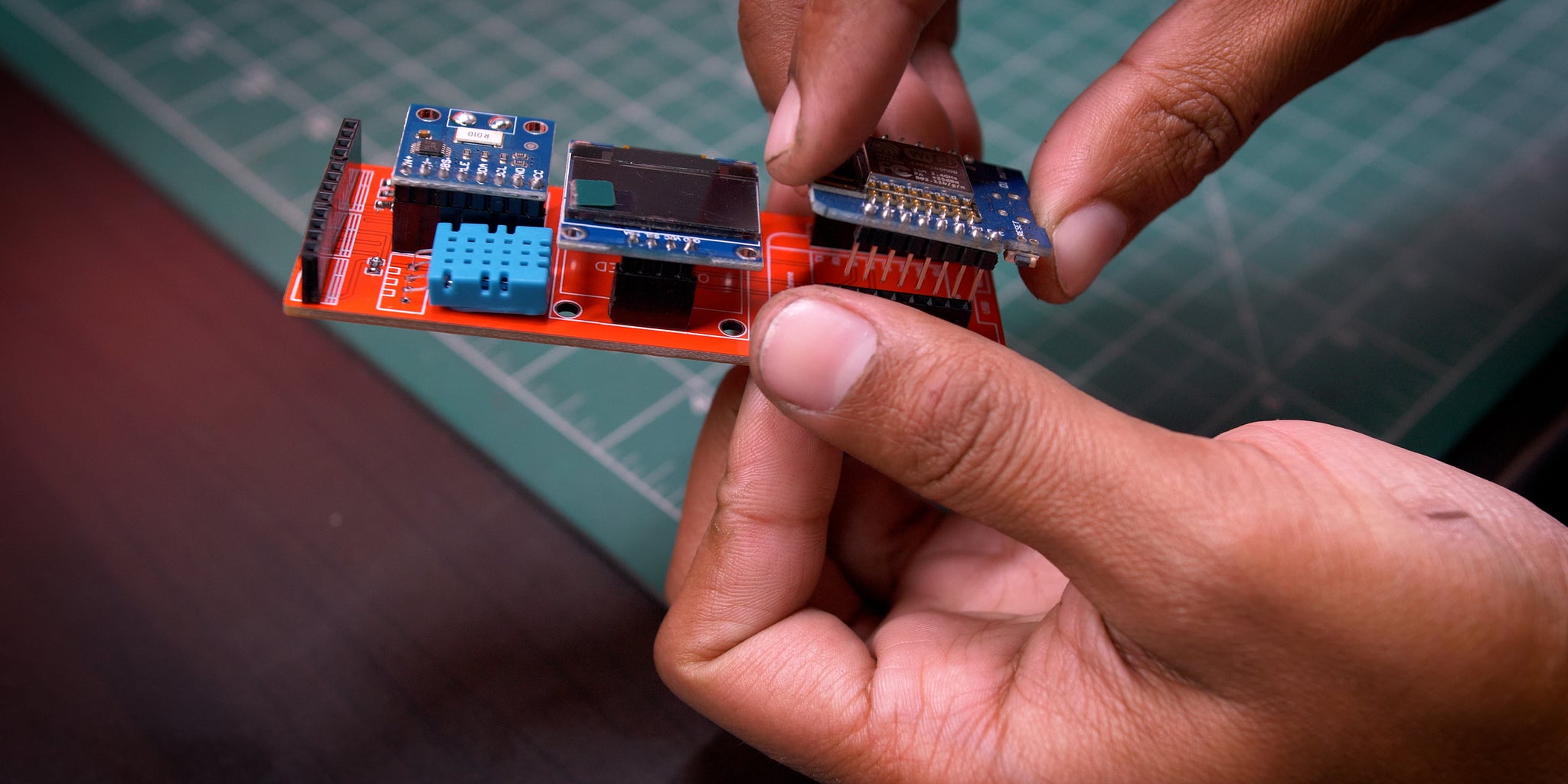
Started with mounting the Old then INA226 and then ESP8266 Module
Note - Please see the images for better understanding
Step 9: Removing the OLD Shunt Resistance

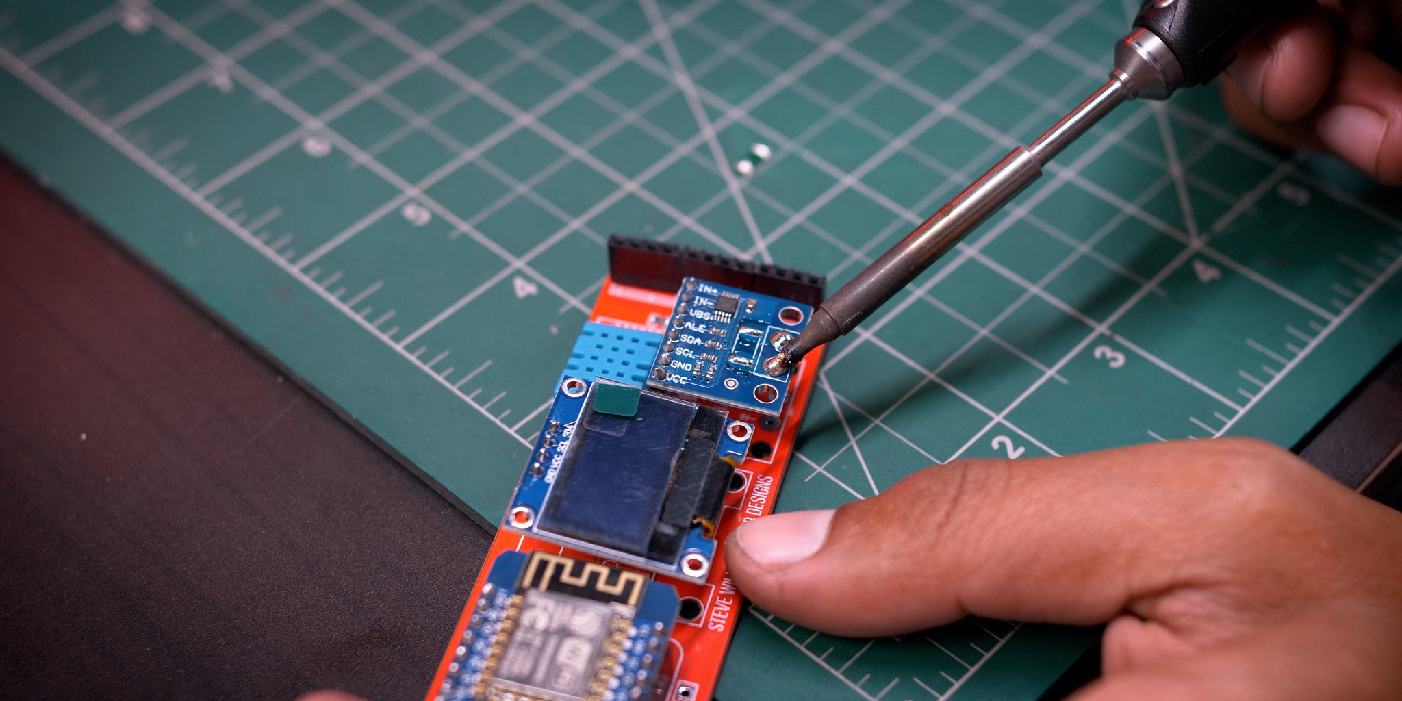
It's very necessary to remove the On-Board resistance later we are gonna use a 100A Shunt
Note - Please see the images for better understanding
Step 10: Unnecessary Stuff :p
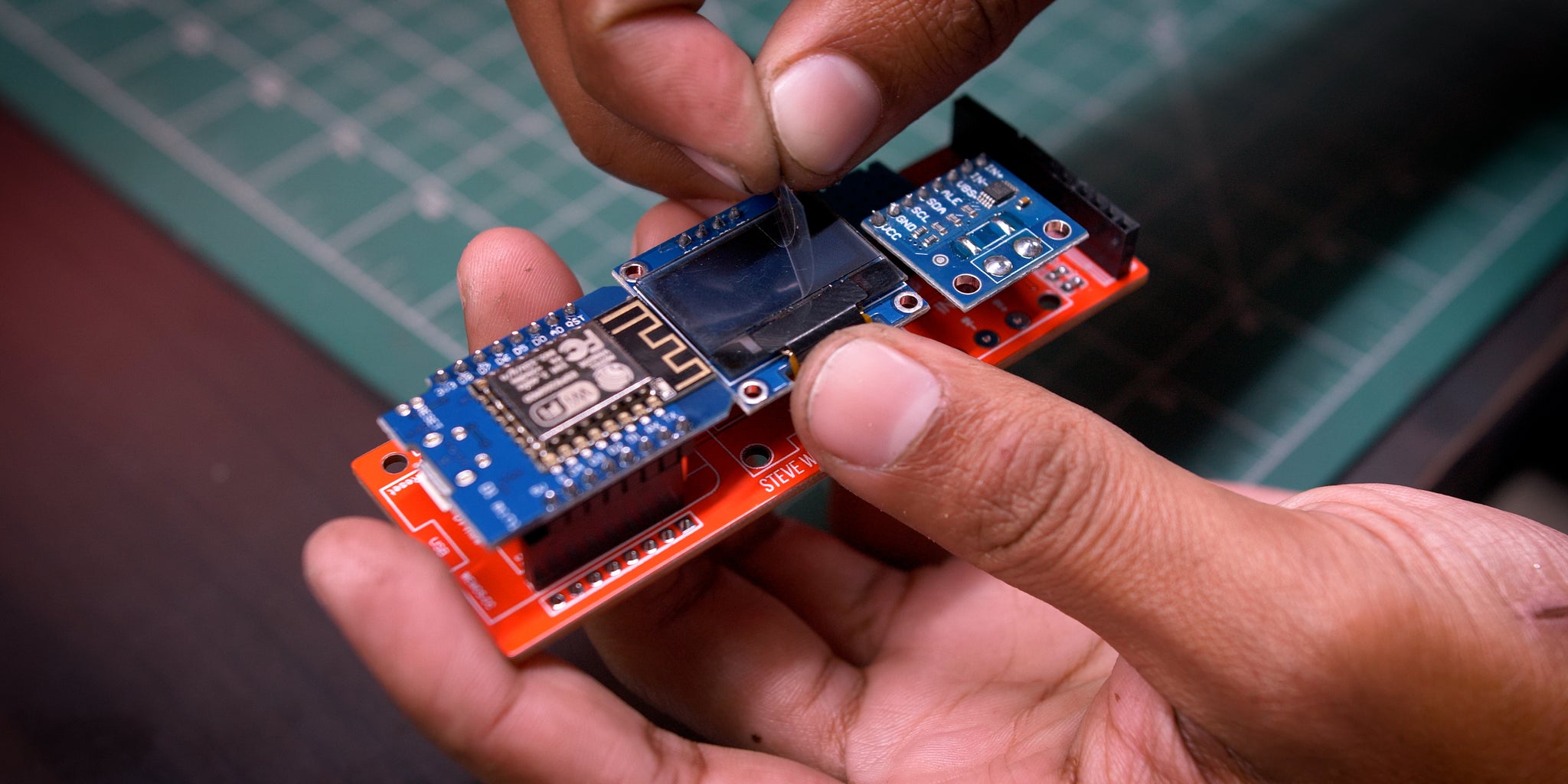

Pealing off the protective film is fun :p
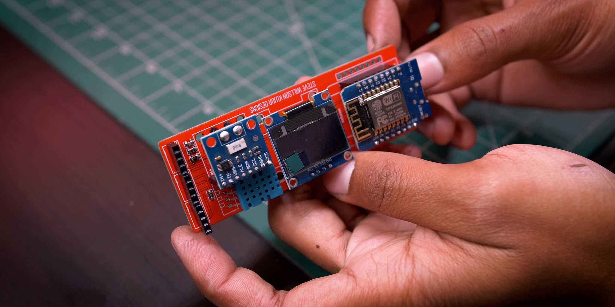
Step 11: Finished PCB
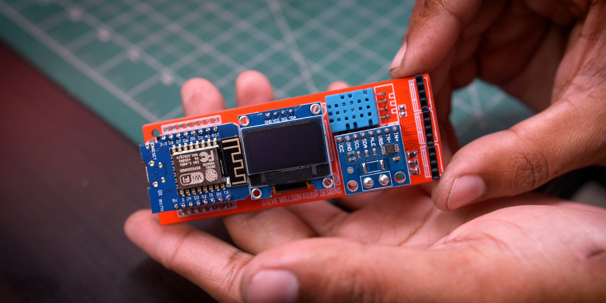

All set for Programming
Step 12: Programming


After Plugging the USB into the computer I use Tasmotizer to Flash .bin files
Step 13: First Boot Up


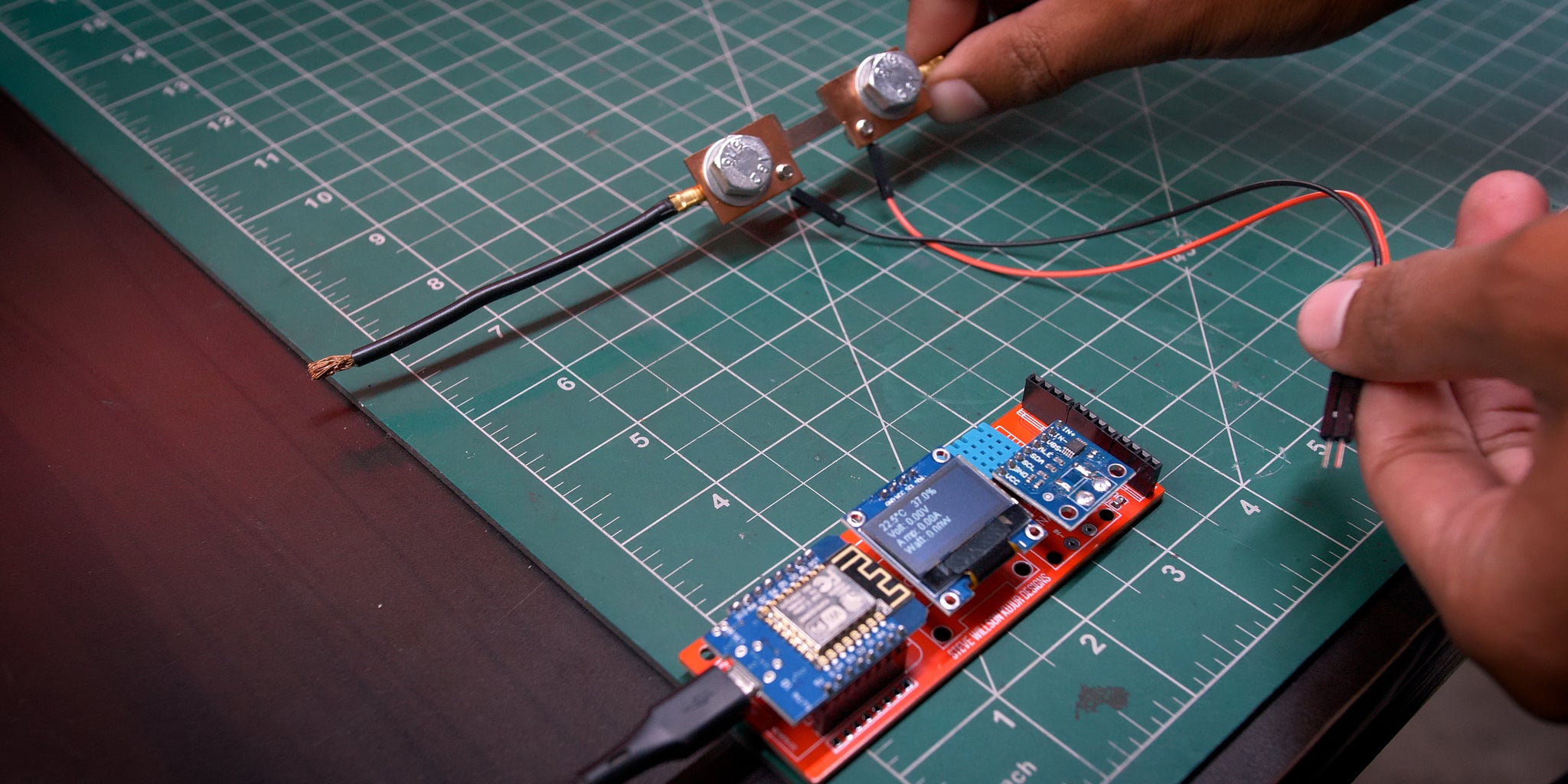
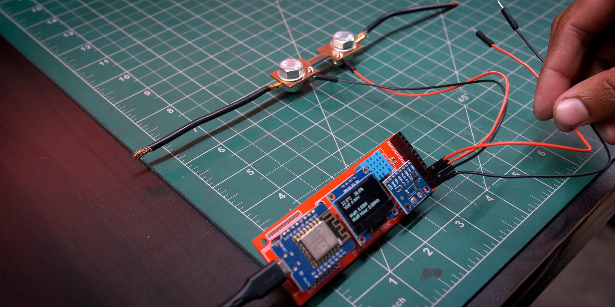
You'll be welcomed with cute little 0.96" Oled showing data
Wait for 30 Second and you'll see Current Temperature & Humidity
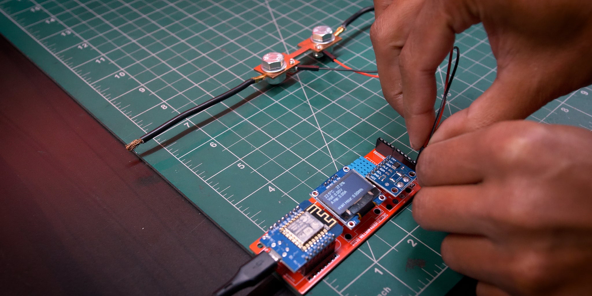
Step 14: Wiring Diagram
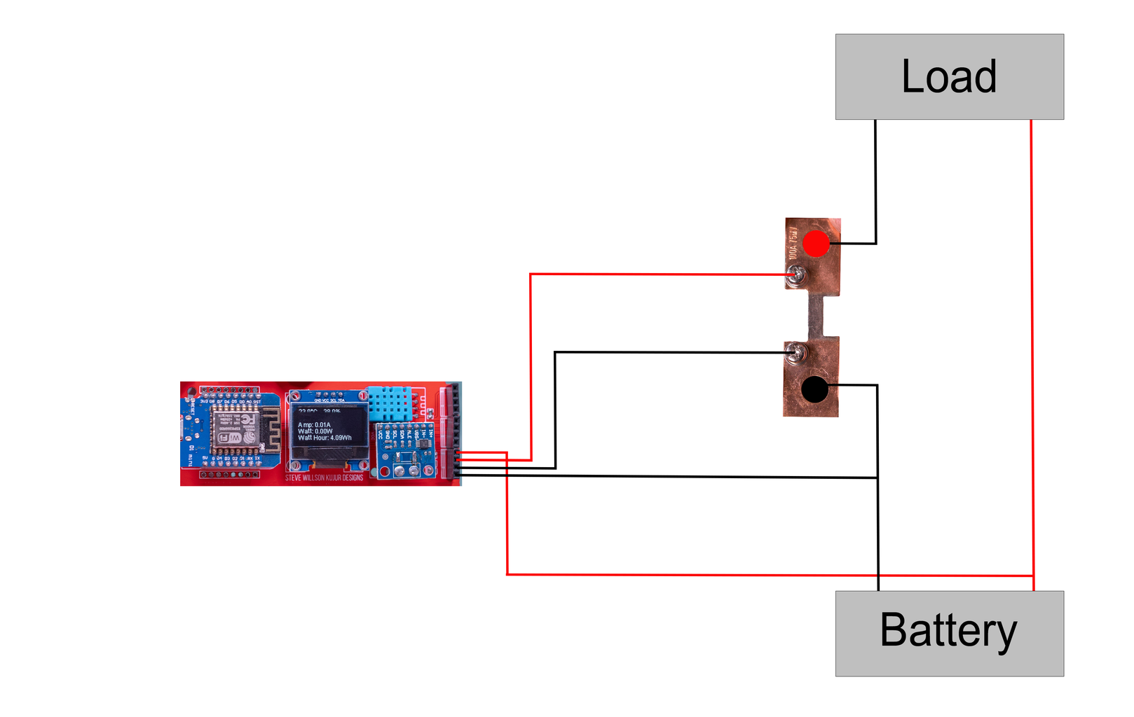
Note - Please see the images for better understanding
Step 15: Preparing Shunt


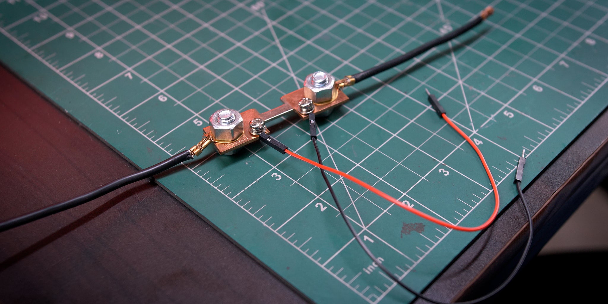

Note - Please see the images for better understanding
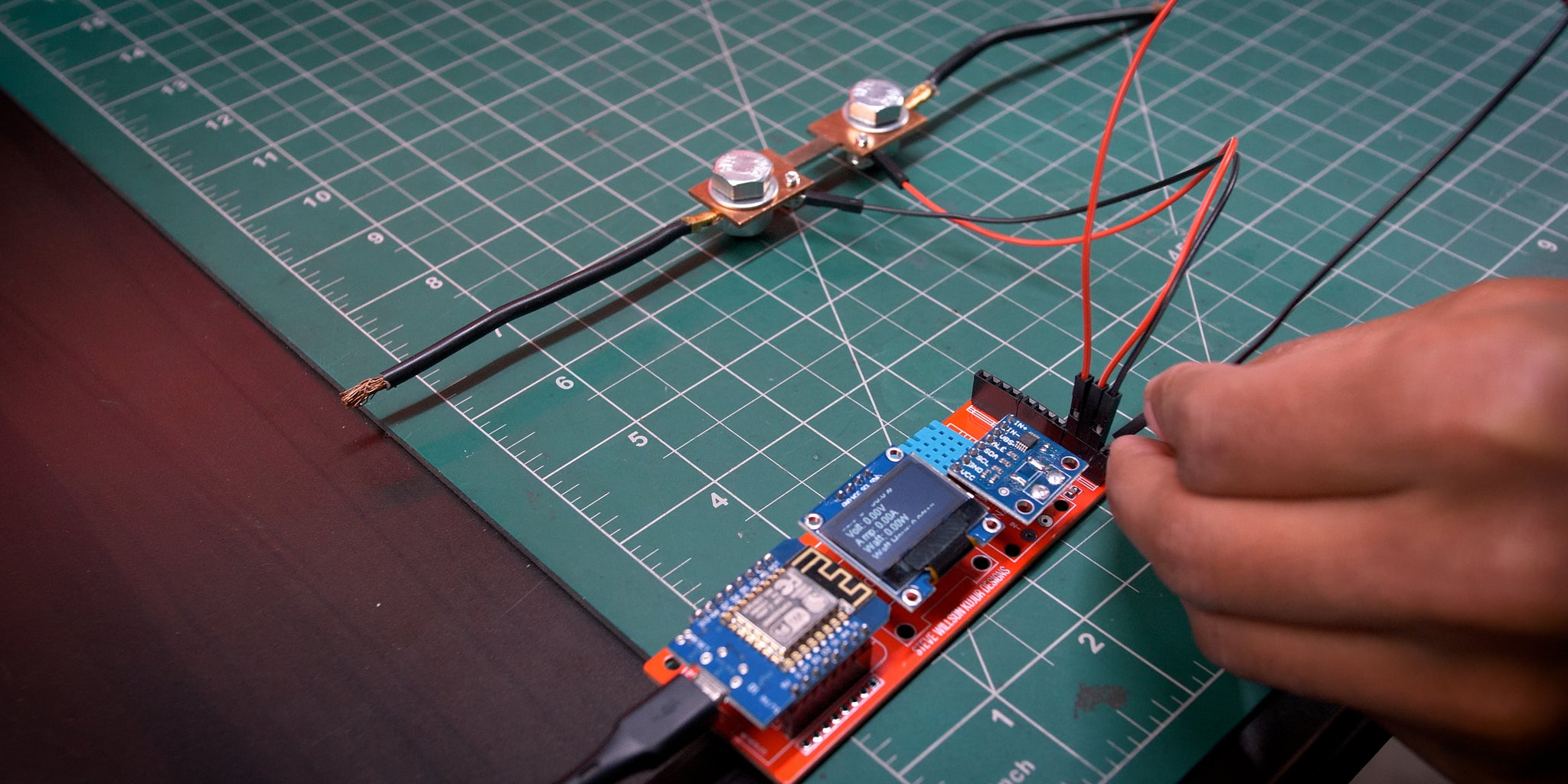
Step 16: Finishing Up
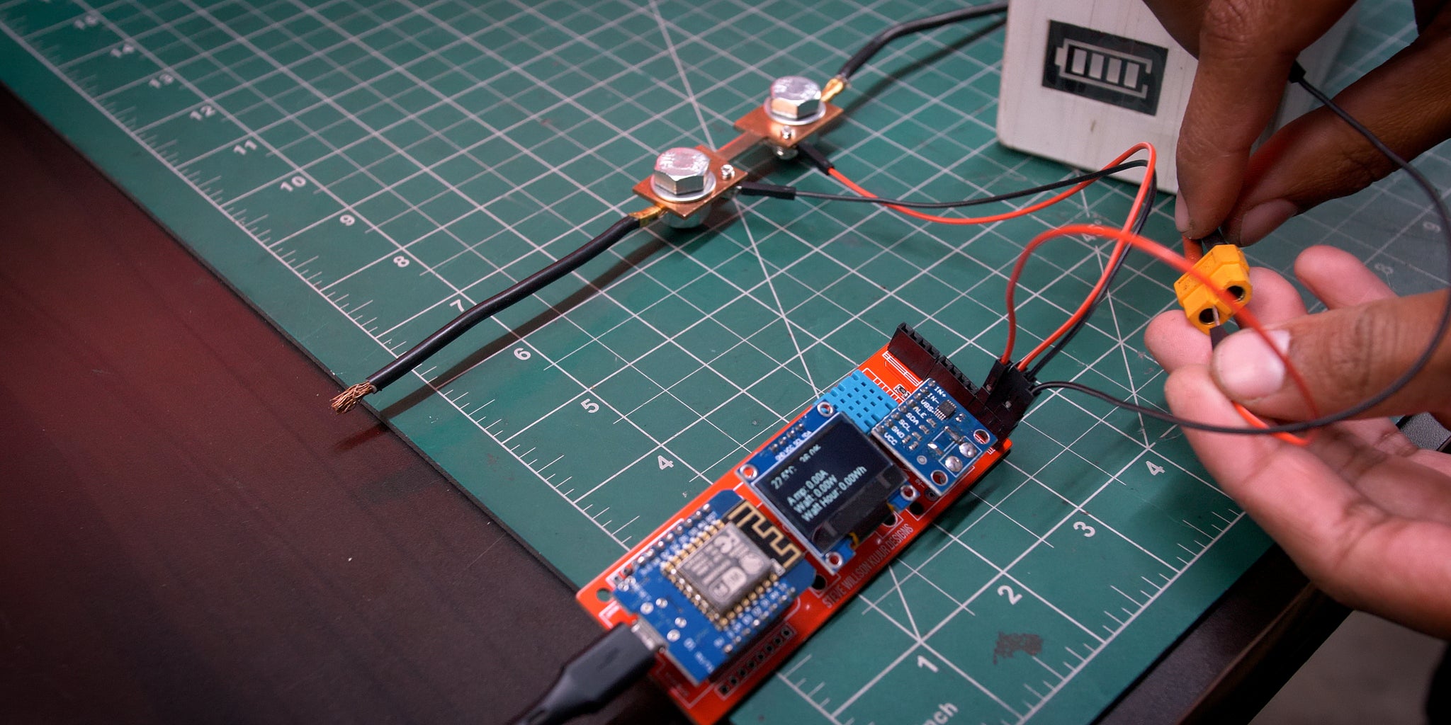
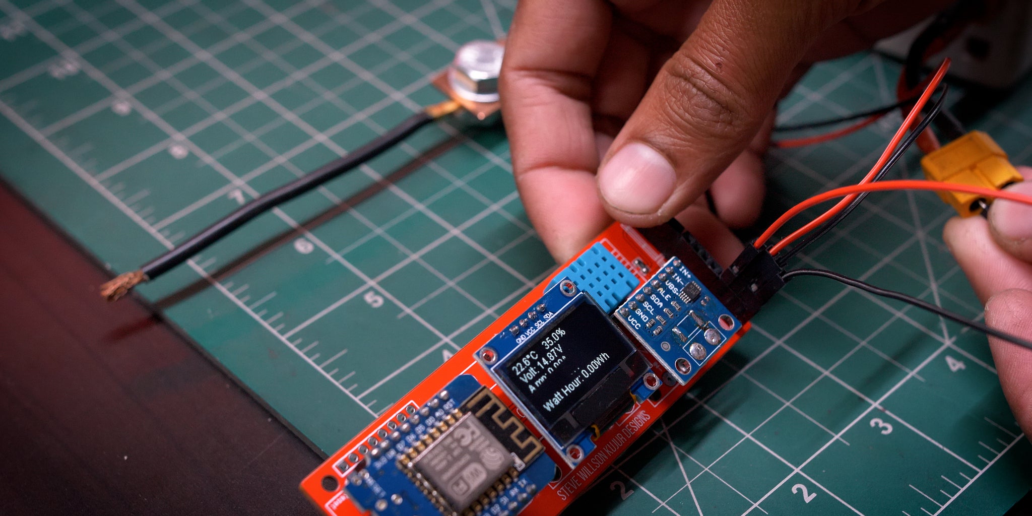

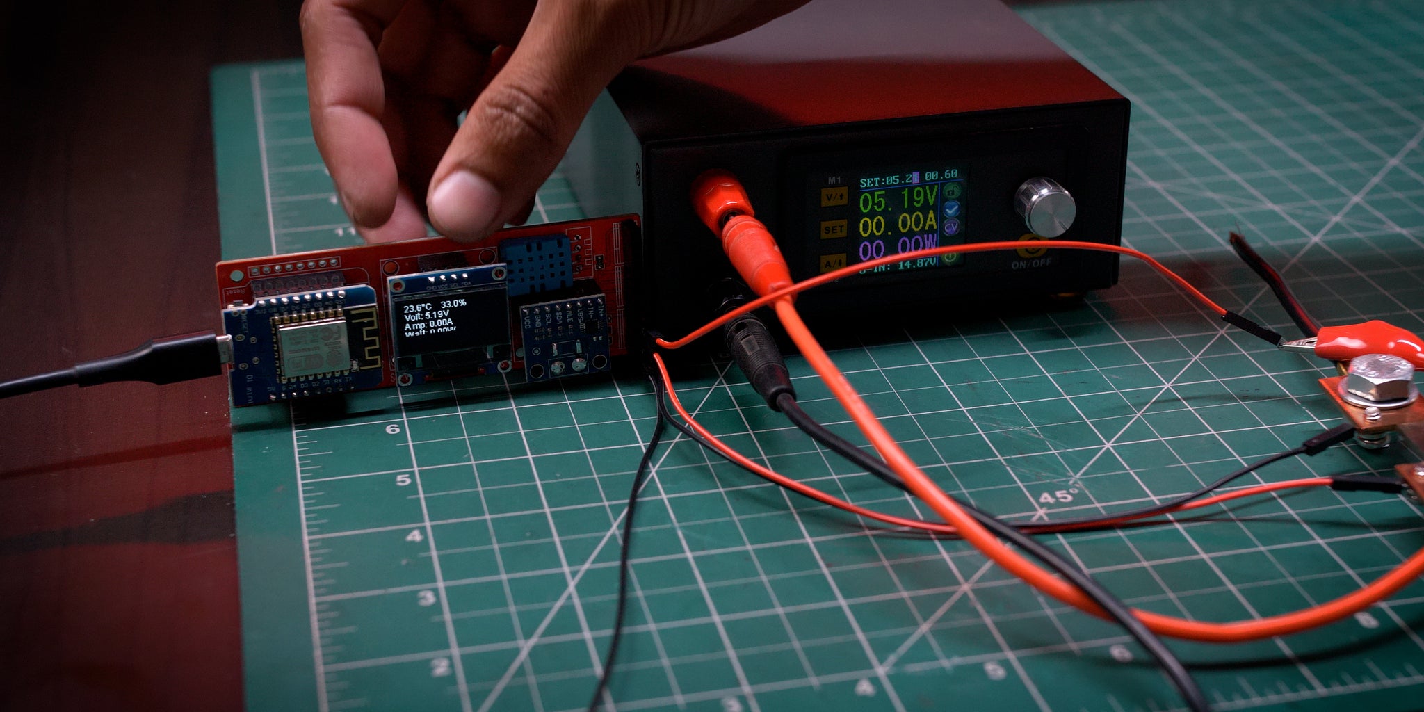
You can see everything is working and precise
That's all for today guys!
Click Here to See The Video
You Just Made It Thank you for visiting my Instructables Stay tuned for the next Projects


