

Introduction: DMX Ardweeny Node


Hi Instructable..ers,
I've settled on the lighting industry standard of DMX as my overall control protocol as I explore the world of blinky lights. This universal control method is electrically robust, radio transmissible, and flexible enough for my needs (not to mention the needs of major concert, theatrical, and entertainment venues.) There are a variety of DMX sequence controllers from free to thousands of dollars.
To that end, I designed a single-board DMX receiver that serves a Solarbotics Ardweeny daughter-board. It features;
o an on-board 5V power regulator - 1AMP capacity
o 5V header for powering other devices (or it can serve to power this board from another regulated supply.)
o opto-isolation to protect the Ardweeny from spikes on the DMX lines
o Arduino analog and digital pin-outs for controlling other gear with your Arduino sketches
o RJ45 jacks for DMX connections (using low-cost Ethernet cables popular amongst lighting hobbyists)
o no DMX termination on board (be sure to place a 120ohm resistor across the last jack in a series)
o on-board PROGRAM/RUN slide switch that disconnects the DMX line from the Ardweeny so you can program it via the ICSP header.
Just rewrite the Arduino code to control any device with DMX.
design references:
DIYLightAnimation.com - The excellent kits designed by Robert Jordon and other amazing contributors. I currently own the EtherDongle, Rx/Tx transmitter/receivers, and Lynx Express 16-channel dimming system.
Arduino.cc (of course)
Matthias Hertel, http://www.mathertel.de - who has written the most effective DMX sender/receiver library I've found to-date.
major design decisions included;
o feed DMX to the flexible Arduino platform
o build cost less than any similar offering (this comes in at $33 with my volume purchased parts from ebay/China)
o through-hole design for easy assembly
o RJ45 jacks rather than XLR to take advantage of lower-cost Ethernet cables
o can provide power on the board for low-amperage projects or can be powered by larger supplies
o DMX isolation to protect the Ardweeny from transients (I also have a version with power isolation)
o Ardweeny can be easily replaced if damaged
very basic design steps:
o settled on design parameters (above)
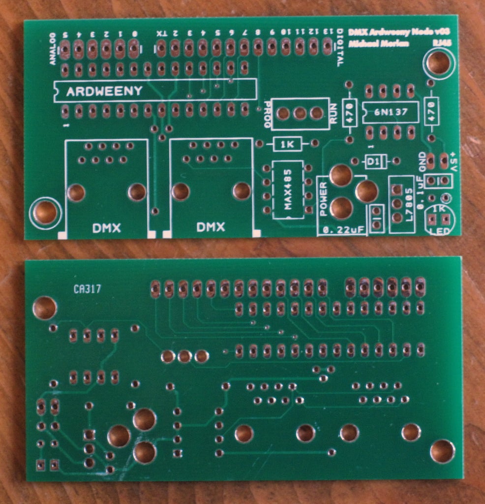
o designed schematic and PCB in SparkfunPCB - a free PCB design tool
o checked fit of all components by printing the PCB to paper and punching parts through the printout
o considered burning the PCB at home but backed off due to the tight double-sided tolerances of some of the small vias
o submitted the Gerber design output files to BatchPCB.com (a service of SparkFun Electronics)
o received the PCB boards and populated one
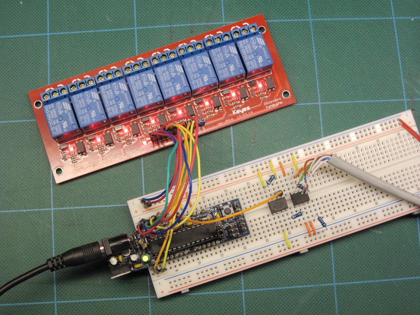
Here's a very simple Arduino sketch that controls the 8-channel relay board in the photo. (You'll need to install the DMXSerial library written by Matthias Hertel at http://www.mathertel.de.)
---------------------------------------------------------------------------------------------------------------------
// DMX_Relay_8ch_v01 - September 15, 2012
// receives DMX data and operates an 8-channnel relay board via digital outs
//
// DMX routines Copyright (c) 2011 by Matthias Hertel, http://www.mathertel.de
//
#include
//this device's DMX start address
#define DMX_START_ADDRESS 1
// number of DMX channels to reserve for this device
#define DMX_NUM_CHANNELS 8
//output pin setup (The number of indices in the array should match DMX_NUM_CHANNELS.)
byte relay_pin[DMX_NUM_CHANNELS] = {2,3,4,5,6,7,8,9};
void setup()
{
//initialize DMX receiver
DMXSerial.init(DMXReceiver);
//initialize pin outputs
for (int p=0; p
pinMode(relay_pin[p], OUTPUT);
digitalWrite(relay_pin[p], LOW);
}
}
void loop()
{
for (int p=0; p
if (DMXSerial.read(DMX_START_ADDRESS+p) < 128)
{
digitalWrite(relay_pin[p], LOW);
}
else
{
digitalWrite(relay_pin[p], HIGH);
}
}
}
---------------------------------------------------------------------------------------------------------------------
If you want to try this project:
I have some spare PCB's or you can order one at BatchPCB.com: https://batchpcb.com/pcbs/97418
I might sell a complete PCB/parts kit. Ask me.
Bill of Materials
1x PCB via BatchPCB.com
1x Solarbotics part # KARDW
1x GN137 Opto Coupler DIP-8
1x MAX485EPA RS485 DIP-8
1x L7805ABV Voltage Regulator 5V 1A TO220
1x 1Kohm Resistor
2x 470ohm Resistor
1x 0.1uF ceramic capacitor
1x 0.33uF ceramic capacitor
1x IN4001 diode
1x 5mm red LED
1x Header 2-pin 0.1 spacing
1x Header 6-pin 0.1 spacing
1x Header 13-pin 0.1 spacing
1x 5.5mm barrel jack - Spark Fun Electronics SKU : PRT-00119
2x RJ45 PCB jack, right-angle, no shield
1x SPDT slide switch or 2-pos header with jumper
Michael


