

Introduction: Darth Vader Chest Box


To be able to mimic Darth Vader during a party or any other occasion can be a lot of fun. Unfortunately commercial solutions are costly. The Hasbro Star Wars Darth Vader Voice Changer costs almost $300 on Amazon. In this instructable will explain how to make a cheap Darth Vader Chest Box that, with a microphone attached to it, changes your voice to Darth Vader's. As a bonus other effects can be selected on the Chest Box such as robot and high pitched voice.
To make this Chest Box as shown it is essential to have access to a laser cutter. Laser cutters are becoming more and more available for hobbyists. A laser cutter can be found at your local FabLab or Maker Space. If you don't have access to a laser cutter you can of course make a wooden or plastic box by hand. It is also essential to have basic understanding of electronics and have soldering skills to solder the components to the perf-board.
A bench power supply is very helpful in this project but the Chest Box can be finished without it. If you don't have a bench power supply use the battery holder with the three AA batteries or use a multi voltage power supply and cut off the plug.
One part, the one that holds the headphone jack plug, was made with a 3d printer. If you don't have a 3d printer available you can order this part from 3d printer services like Shapeways or 3dHubs. You can even omit this part all together and adjust to plywood to fit the jack plug
If you're interested in the development of this Darth Vader Chest Box (and an older one) go to my blog at eribuijs.blogspot.com and search for Darth Vader.
Step 1: Parts
I provided a file with all the components (electronic and other) that you need for this project. For some of the parts I added a link to a supplier in the file. This is by no means the only supplier so feel free to shop around for a better price or delivery conditions. The main electronic part is the voice modulator chip, the HT8950A. It's producer, Realtek, also has a similar chip the HT8950, an 18-DIP chip. Although this chip can be used it's pin layout differs from the HT8950A. If you want to use the schematics that I provide make sure that you buy the HT8950A.
Attachments

Step 2: Building and Testing the Electronic Circuit


Before I solder the electronic parts to the perf board I always build and test the circuit on a breadboard. This ensures that the electronic circuit works as expected and components are easily exchanged in case I want to experiment with the circuit. Carefully check the schematics when you plug your electronic components into the breadboard. This circuit can be built in steps making it less overwhelming. First build the circuit needed to run the HT8950A voice modulator without the LM386 amplifier and even without connecting pin 2,3,4 and 5 to the switch buttons. When this part of the circuit is ready plug the microphone into the breadboard (or use some other audio-in). Now connect the speaker with one wire connected to pin 12 (AUDIO) and another to ground. Apply power with three AAA batteries or use a power bench (4.5V DC). If everything is fine the voice modulator should now operate but only in Robot mode (this is the default mode on start-up). The LED between the pin 14 (TS) and pin 11 (LAMP) should be flickering when audio is received, a sign that the modulator is working. Due to it's built-in amplification the sound of the HT8950A is audible but barely (it is better when a headphone is connected). With the HT8950A working you can move on to the next step. If this part of the circuit doesn't work carefully check the components and the way they are connected. Again compare it to the schematics.
Next connect pin 2,3,4 and 5 to the buttons. Now the pitch can be increased and decreased (pin 3 and 4) and the modulator can be switched from Robot (pin 2). The Vibrato button connected to pin 5 toggles the Vibrato mode on and off. With all the functions of the HT8950A working you can move on to the next step.
Lastly add the LM386 amplifier. Pin 3 of the amplifier is connected to the output of the HT8950A. With the amplifier connected add the speaker and test the circuit. The volume of the sound can be controlled with the 250ohm potentiometer. At this point the circuit should be fully functional and you can move on to the next step.

Step 3: Soldering the Circuit


First cut the perf board to a size of 10x2.5cm (4"x1") Push the pins of the switch buttons through the perf board and solder the wires to the pins. When finished continue with the perma proto board (see the parts list). Place the board next to the breadboard as shown in the image above. Since the layouts of the breadboard and the perma proto board are identical you can simply copy what has been done on the breadboard. Soldering the board can be done in the same steps as described previous step. Place the DIP-16 socket for the HT8950A first and subsequently solder all the supporting components connected to it. Test the HT8950A before moving to the LM386 amplifier (see the previous step for this). Use the DIP-8 socket for the LM386 instead of soldering the amplifier directly to the board. As a rule I always solder a couple of components and check them carefully (with a magnifying glass if necessary) before moving on.
When the soldering of the perma proto board is finished test it with the speaker and audio-in attached. Without the switch buttons attached it should be operating in Robot mode. Next solder the wires from the four switch buttons to the pins 2,3,4 and 5. Finally solder the wires for the speaker, on/off switch, battery holder and audio-in to the perma proto board. The soldering of these speaker, on/off and switch audio-in is left to the assembly step. The battery holder can be soldered to the wires because it sits in the enclosure with the board.
Step 4: Making the Plywood Enclosure


For the plywood enclosure I first created a model using the handy Makercase website. I choose a 6mm thickness of material and finger type edge joints. Makercase can creates .svg files (with the Generate Laser Cutter Case button) that can be imported in Inkscape (which is a free) or another illustration program. I modified the design in Inkscape until it resembled the Darth Vader Chest Box. I added both .eps and .svg file below. Most laser cutters accept .eps files but you may want to check this first. The .svg file can be used to alter the design or to export a file to a file type that your laser cutter accepts. The black colored lines on the drawing need to be cut while the red colored lines need to be engraved. Make sure that your laser cutter handles these colors accordingly. The handling from laser cutters differ from type to type so you have to rely on the support at the Fablab.
I also added an .stl file for the part that hold the headphone jack plug. The headphone jack can be screwed into this part. The part will fit into the top of the enclosure and can be fastened with two m3 machine screws and nuts.
NOTE: some of your external parts, such as switch buttons and SPST switch, can differ in shape from the ones that I used. Make sure that you adjust the .svg file accordingly before cutting the plywood.

Step 5: Assembly

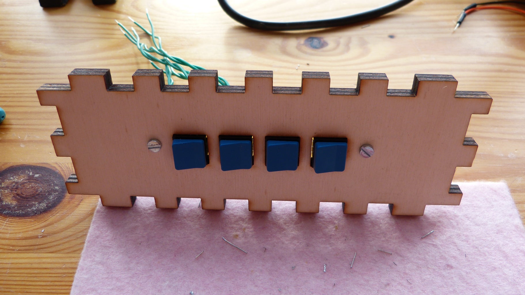
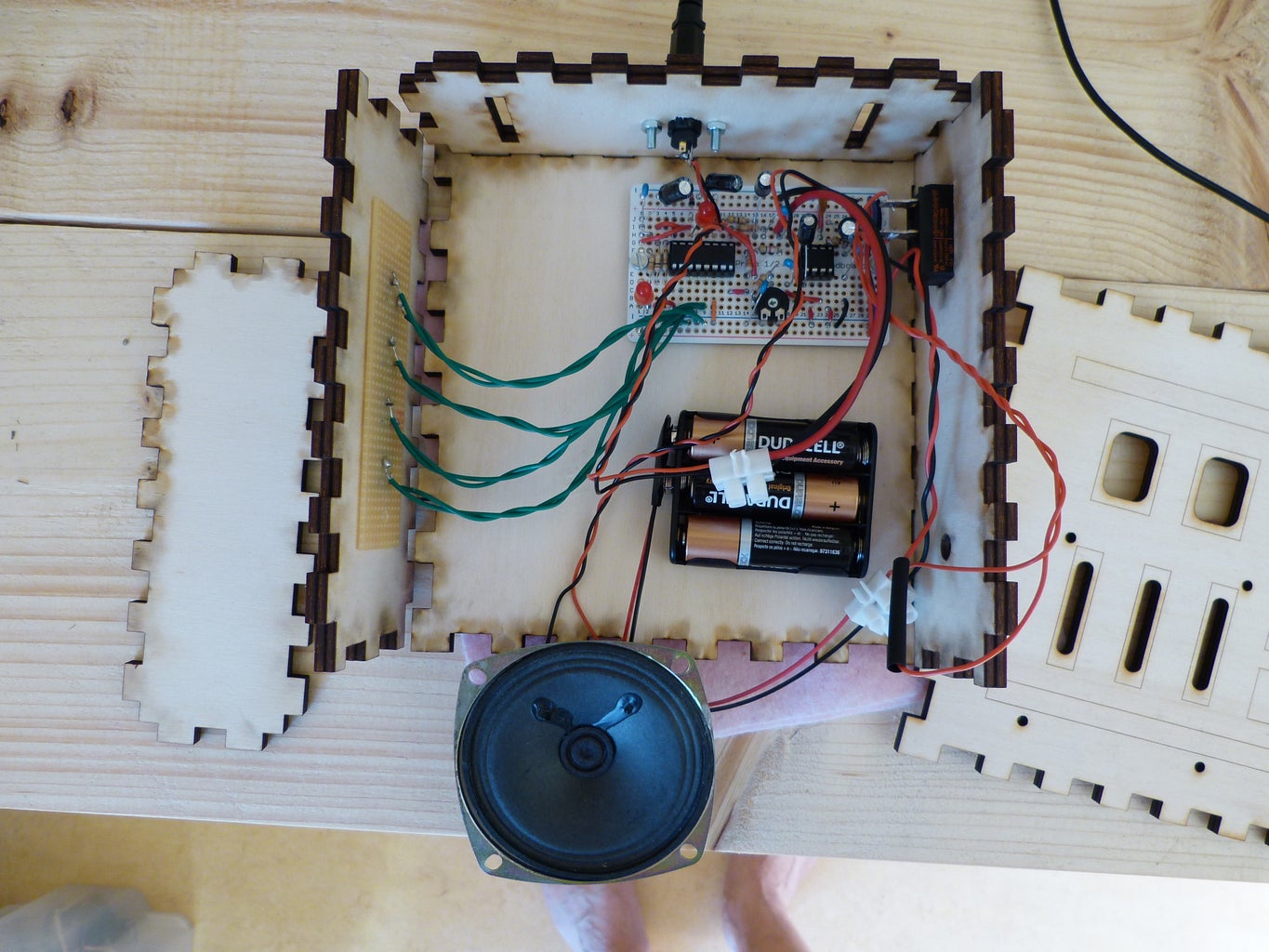

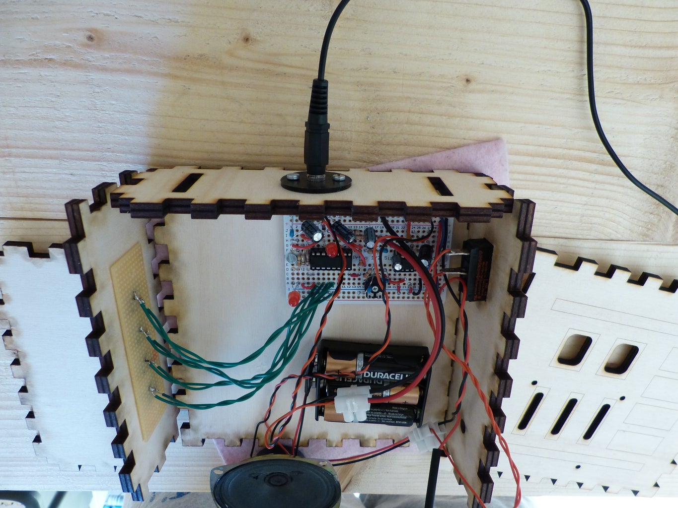
First insert the switch buttons that are mounted on the perf board into the squares of the side panel. Drill two 3mm holes through the perf board and the panel. The 10x2.5cm perf board can now be fastened to the side panel with two 3x12mm machine screws and bolts. The speaker is fastened to the front board using four 3x12mm machine screws and bolts. The head phone jack plug is inserted into the 3d printed jack holder. Drill two 3mm holes in the top panel using the jack holder for the position of the holes. The jack holder is then fastened to the top panel with two 3x12mm machine screw and bolts. The perma proto board and the battery holder are fastened to the back board with two 3x12mm machine screws and bolts each (again drill 3mm holes on the appropriate positions). Next the speaker, SPST switch and audio-in are soldered to their respective wires. With all components fastened to the panels can be glued to the each other. Begin with the back and glue all side panels to it and to each other. Finally insert the front panel. Don't glue the front panel it can be used as a service panel in case access to the insides is needed (e.g. to change batteries).
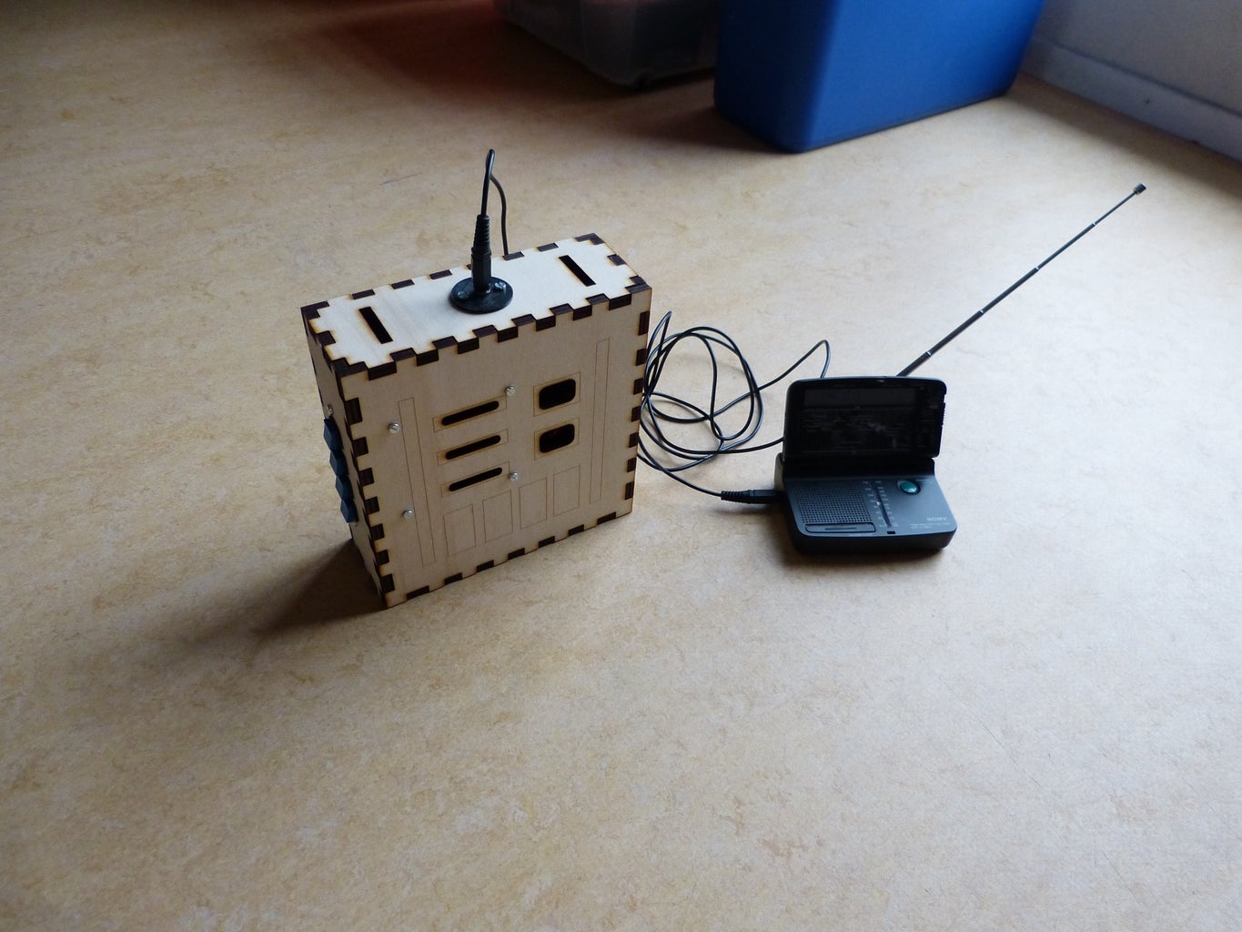
The basic Chest Box is now ready. If you want you can enhance it e.g. with paint or additional LED's. I added some wooden pieces to the front to provide the Darth Vader Chest Box some more profile. The top panel has two slits for a carrier band in case you want to wear the Chest box. Good luck and have fun.


![Tim's Mechanical Spider Leg [LU9685-20CU]](https://content.instructables.com/FFB/5R4I/LVKZ6G6R/FFB5R4ILVKZ6G6R.png?auto=webp&crop=1.2%3A1&frame=1&width=306)


