

Introduction: Disco LED Party Cup!


Welcome to my inscrutable for the 'Disco LED Party Cup!' use it at parties or to add some excitement to a quiet night in! The bottom 'puck' clips onto the bottom of a plastic party cup and lights up to the beat!
Step 1: Parts List

First thing you need to take care of is gathering parts, all the parts needed are included below!
Electronics Parts
380mah LiPo battery - http://www.robotshop.com/uk/hubsan-fpv-x4-mini-qu...
TP4056 LiPo charge controller - http://www.geekbuying.com/item/TP4056-1A-3-7V-Lip...
MAX4466 Microphone Amplifier - https://www.adafruit.com/product/1063
5v Boost Converter - http://www.dx.com/p/usb-dc-1-5v-to-dc-5v-voltage-...
Arduino Nano v3 - https://www.arduino.cc/en/Main/ArduinoBoardNano
Neopixel ring - https://www.adafruit.com/products/1643
Hardware Parts
3D Printed Enclosure - (Download the STL and Fusion 360 Model)
Step 2: Wiring the Electronics


The Arduino micro-controller is the brains of the operation which takes the analog input from the microphone and converts into a digital signal which powers the Neopixel LEDs. The LiPo battery lets us take our party cup anywhere without an annoying cable getting in the way of our awesome dance moves! I used silicone wire as it makes stuffing all the electronics into the case much easier and is really nice to work with. Fancy.
The basic circuit follows this system;
TP4056 LiPo charge controller --> LiPo Battery --> 5v Boost Converter --> Arduino Nano --> Microphone Amp --> Neopixel LED Ring
Connect the 3.3v and REF pins together on the Arduino
The Microphone module connects to 3.3v, GND and A0 on the Arduino.
The Neopixel Ring connects to 5v, GND, and Digital pin 6 on the Arduino.
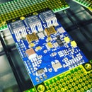
The boost converter and lipo charger are daisy chained together, the photo shows how it's connected.
Add some heat shrink to prevent shorts and an on off switch in line with the battery.
Electronics - DONE!
Step 3: Program the Arduino

We need to program the Arduino so it knows what to do with our mic and LEDs. I have modified the Adafruit code slightly for our 5v Arduino. Just connect your Arduino Nano to your computer and upload this code!
Remember to switch it on to make sure its working well!
/*
LED VU meter for Arduino and Adafruit NeoPixel LEDs.

Hardware requirements:
 - Most Arduino or Arduino-compatible boards (ATmega 328P or better).
 - Adafruit Electret Microphone Amplifier (ID: 1063)
 - Adafruit Flora RGB Smart Pixels (ID: 1260)
   OR
 - Adafruit NeoPixel Digital LED strip (ID: 1138)
 - Optional: battery for portable use (else power through USB or adapter)
Software requirements:
 - Adafruit NeoPixel library

Connections:
 - 3.3V to mic amp +
 - GND to mic amp -
 - Analog pin to microphone output (configurable below)
 - Digital pin to LED data input (configurable below)
 See notes in setup() regarding 5V vs. 3.3V boards - there may be an
 extra connection to make and one line of code to enable or disable.

Written by Adafruit Industries.  Distributed under the BSD license.
This paragraph must be included in any redistribution.
*/

#include

#define N_PIXELS  12  // Number of pixels in strand
#define MIC_PIN   A0  // Microphone is attached to this analog pin
#define LED_PIN    6  // NeoPixel LED strand is connected to this pin
#define DC_OFFSET  0  // DC offset in mic signal - if unusure, leave 0
#define NOISE     10  // Noise/hum/interference in mic signal
#define SAMPLES   60  // Length of buffer for dynamic level adjustment
#define TOP       (N_PIXELS + 2) // Allow dot to go slightly off scale
#define PEAK_FALL 40  // Rate of peak falling dot

byte
  peak      = 0,      // Used for falling dot
  dotCount  = 0,      // Frame counter for delaying dot-falling speed
  volCount  = 0;      // Frame counter for storing past volume data
int
  vol[SAMPLES],       // Collection of prior volume samples
  lvl       = 10,      // Current "dampened" audio level
  minLvlAvg = 0,      // For dynamic adjustment of graph low & high
  maxLvlAvg = 512;
Adafruit_NeoPixel
  strip = Adafruit_NeoPixel(N_PIXELS, LED_PIN, NEO_GRB + NEO_KHZ800);

void setup() {

  // This is only needed on 5V Arduinos (Uno, Leonardo, etc.).
  // Connect 3.3V to mic AND TO AREF ON ARDUINO and enable this
  // line.  Audio samples are 'cleaner' at 3.3V.
  // COMMENT OUT THIS LINE FOR 3.3V ARDUINOS (FLORA, ETC.):
 analogReference(EXTERNAL);

  memset(vol, 0, sizeof(vol));
  strip.begin();
}

void loop() {
  uint8_t  i;
  uint16_t minLvl, maxLvl;
  int      n, height;


  n   = analogRead(MIC_PIN);                        // Raw reading from mic
  n   = abs(n - 512 - DC_OFFSET); // Center on zero
  n   = (n <= NOISE) ? 0 : (n - NOISE);             // Remove noise/hum
  lvl = ((lvl * 7) + n) >> 3;    // "Dampened" reading (else looks twitchy)

  // Calculate bar height based on dynamic min/max levels (fixed point):
  height = TOP * (lvl - minLvlAvg) / (long)(maxLvlAvg - minLvlAvg);

  if(height < 0L)       height = 0;      // Clip output
  else if(height > TOP) height = TOP;
  if(height > peak)     peak   = height; // Keep 'peak' dot at top


  // Color pixels based on rainbow gradient
  for(i=0; i= height)               strip.setPixelColor(i,   0,   0, 0);
    else strip.setPixelColor(i,Wheel(map(i,0,strip.numPixels()-1,30,150)));

  }


  // Draw peak dot
  if(peak > 0 && peak <= N_PIXELS-1) strip.setPixelColor(peak,Wheel(map(peak,0,strip.numPixels()-1,30,150)));

   strip.show(); // Update strip

// Every few frames, make the peak pixel drop by 1:

    if(++dotCount >= PEAK_FALL) { //fall rate

      if(peak > 0) peak--;
      dotCount = 0;
    }


  vol[volCount] = n;                      // Save sample for dynamic leveling
  if(++volCount >= SAMPLES) volCount = 0; // Advance/rollover sample counter

  // Get volume range of prior frames
  minLvl = maxLvl = vol[0];
  for(i=1; i maxLvl) maxLvl = vol[i];
  }
  // minLvl and maxLvl indicate the volume range over prior frames, used
  // for vertically scaling the output graph (so it looks interesting
  // regardless of volume level).  If they're too close together though
  // (e.g. at very low volume levels) the graph becomes super coarse
  // and 'jumpy'...so keep some minimum distance between them (this
  // also lets the graph go to zero when no sound is playing):
  if((maxLvl - minLvl) < TOP) maxLvl = minLvl + TOP;
  minLvlAvg = (minLvlAvg * 63 + minLvl) >> 6; // Dampen min/max levels
  maxLvlAvg = (maxLvlAvg * 63 + maxLvl) >> 6; // (fake rolling average)

}

// Input a value 0 to 255 to get a color value.
// The colors are a transition r - g - b - back to r.
uint32_t Wheel(byte WheelPos) {
  if(WheelPos < 85) {
   return strip.Color(WheelPos * 3, 255 - WheelPos * 3, 0);
  } else if(WheelPos < 170) {
   WheelPos -= 85;
   return strip.Color(255 - WheelPos * 3, 0, WheelPos * 3);
  } else {
   WheelPos -= 170;
   return strip.Color(0, WheelPos * 3, 255 - WheelPos * 3);
  }
}
Step 4: 3D Print an Enclosure

If you have a 3D printer then this step is easy for you, download the STL file and get printing. If not however you've got some great options, check out ShapeWays or 3D Hubs for a low cost print shipped to you. Easy right!
Depending on what plastic cup your using you might need to modify the design slightly to ensure it clips onto the bottom of the cup. I've included the Fusion 360 file as well as an IGES file.
Grab the Fusion file here! - http://a360.co/23xISj6


Step 5: Stuff It Inside!


Its time to cram all the boards and wire into the case, you should have just enough room to squeeze everything in. I used hot glue to fix everything down which worked really well just be careful not to warp the enclosure if it gets too hot.
I also cut out a plastic disc to cover the top, this isn't really necessary but makes it look much more professional, especially when you add the Instructables logo ;)
Thanks for looking and good luck with your disco cup!


