

Introduction: Fusion Board - 3D Printed Electric Skateboard


This Instructable is an overview of the build process for the Fusion E-Board that I designed and built whilst working at 3D Hubs. The project was commissioned to promote the new HP Multi-Jet Fusion technology offered by 3D Hubs, and to show off multiple 3D printing technologies and how they can be effectively combined.
I designed and built an electric motorised longboard, which can be used for short to moderate journeys or combined with public transport to offer a much wider traveling range. It has a high top speed, is very manoeuvrable and is easily carried when not in use.
Step 1: Design Process


I started the project by identifying the main standard components of the longboard; trucks, deck and wheels. These were off the shelf parts so I used these as the starting point of the design. The first stage was to design the drivetrain, this includes the motor mounts, gearing setup and included some modifications to the trucks. The size and position of the motor mounts would dictate the size and location of the enclosures so it was important that this was completed first. I calculated the desired top speed and torque requirements which then enabled me to select the motors and battery for the board. The gearing ratio was also calculated and the pulley sizes were selected, along with the drive belt length. This enabled me to work out the correct size of the motor mounts which ensured a well tensioned belt.
The next stage was to design the battery and speed controller (ESC) enclosures. The selected deck is predominantly comprised of bamboo so is quite flexible, bending substantially in the middle. This has advantages of being comfortable to ride, as it absorbs the bumps in the road, and doesn't transfer them to the rider. However this also means that a split enclosure is needed to house the battery and electronics, as a full length enclosure wouldn't be able to flex with the board and would make contact with the ground during operation. The electronic speed controllers (ESC) were placed closest to the motors due to electrical constraints. Because the motors are attached via the trucks the position changes during turns, so the enclosure had to be designed to allow for clearance of the motors.
The battery system was placed at the other end of the deck and housed the electronics related to power. This included the battery pack, comprised of 20 Lithium ion 18650 cells, the battery management system, on/off switch and charging socket.
I used Autodesk Fusion360 for the entire design process, this software enabled me to quickly model components inside of the main assembly which speeded up the development time considerably. I also used the simulation features in Fusion360 to ensure the parts would be strong enough, especially the motor mounts. This enabled me to actually reduce the size of the mounts as I could verify the strength and deflection requirements and remove material whilst still maintaining an appropriate safety factor. After the design process was complete it was very easy to export the individual parts for 3D printing.
Step 2: Drivetrain


I completed the build of the drivetrain first, to ensure appropriate clearance for the electronics enclosure. I selected Caliber trucks to use as they have a square profile that was perfect for clamping the motor mounts onto. However the axle was slightly too short to allow the two motors to be used on the same truck, so I needed to extend this to allow the wheels to fit.
I achieved this by cutting down some of the aluminium truck hanger body, exposing more of the steel axle. I then cut most of the axle down, leaving around 10mm that I could then thread with an M8 die.
A coupler could then be screwed on and another threaded axle added to that, effectively extending the axle. I used Loctite 648 retaining compound to permanently secure the coupler and new axle to ensure it would not unscrew during use. This allowed the two motors to fit on the truck and provided plenty of clearance for the wheels.
The drivetrain was primarily printed using HP Multi-Jet Fusion technology, to ensure rigidity and strength during high acceleration and braking, where the largest forces would be transferred.
A special pulley was designed to lock into the rear wheels, which was then connected to the motor pulley with a HTD 5M belt. A 3D printed cover was added to provide protection to the pulley assembly.
Step 3: Rib Enclosures


One of the main design decisions I made was to separate the enclosures, which resulted in a clean look and enabling the flexible deck to function without any added stiffness from the enclosures. I wanted to convey the functional aspects of the HP Multi Jet Fusion technology, so I decided to FDM print the main body of the enclosures which reduced costs, and then used the HP parts to support and clamp them to the deck. This provided an interesting aesthetic whilst also being very functional.
The FDM printed enclosures were split in half to aid in printing as support material could be eliminated from the outside surface. The splitline was carefully positioned to ensure it was hidden by the HP part when clamped to the board. Holes for the motor connections were added and gold plated bullet connectors were glued in place to
Threaded inserts were embedded into the bamboo deck to secure the enclosures to the board, and were sanded flush with the board surface to ensure there was no gap between the deck and enclosure.
Step 4: Electronics


The electronics were carefully chosen to ensure the board was powerful but also intuitive to use. This board could potentially be dangerous if any malfunctions would occur, so reliability is a very important factor.
The battery pack is comprised of 20 individual 18650 Lithium-ion cells which are spot welded together to form a 42v pack. 2 cells are welded in parallel and 10 in series; the cells I used were Sony VTC6. I used a spot welder to weld the nickel tabs to form the pack, as soldering creates too much heat which can damage the cell.
The power from the battery enclosure was transferred to the speed controller box using flat braided cable which was ran just under the grip-tape on the top side of the deck. This allowed the cables to be ‘hidden’ and eliminated the need to run cables on the underside which would have looked ugly.
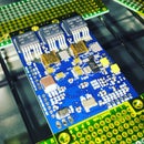
As this is a dual motor board two speed controllers are required to independently control each motor. I used the VESC speed controller for this build, which is a controller specifically designed for electric skateboards which makes it very reliable for this use.
The motors used are 170kv 5065 out-runners which can produce 2200W each, which is a lot of power for this board. With the current gearing setup the boards max speed is around 35MPH, and accelerates very quickly.
The last stage was to create a remote to control the board. A wireless system was preferred due to the easier operation. However it was important to ensure high reliability of transmission as a drop in communication could have serious safety issues, especially at high speeds. After testing a few radio transmission protocols I decided 2.4GHz radio frequency would be the most reliable for this project. I used an off the shelf RC car transmitter, but significantly reduced the size by transferring the electronics to a small hand held case which was 3D printed.
Step 5: Finished Board & Promo Video


The project is now finished! We created a pretty awesome video of the board in action, you can check it out below. Big thanks to 3D Hubs for enabling me to do this project - check them out here for all your 3D printing needs! 3dhubs.com

Participated in the
Make it Move Contest


