

Introduction: ESP32 Joystick Hand Controller ESP-NOW
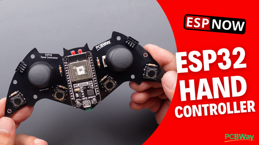


I designed an ESP32 joystick hand controller to wirelessly control the ESP32 Mecanum Wheels (instructables.com/ESP32-Mecanum-Wheels-Robot-and-Bluetooth-Gamepad) robot without using an app. This hand controller is bat-themed and features two thumb joysticks and 4 push-buttons. Check out the video to see how it works...
Step 1: How It Works?
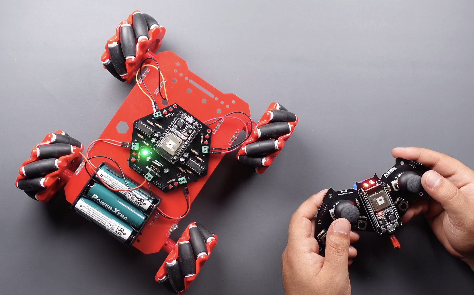
As seen in the video, I control the mecanum wheels robot wirelessly using joysticks. Here, no radio frequency or Wi-Fi was used for communication, communication was provided via the MAC address, which is easier and safer. There is a way to facilitate this communication ESP-NOW... We can communicate with two ESP32 boards, one-way and two-way.
Step 2: Printed Circuit Board
The joystick hand controller was made by many makers, usually using an Arduino Nano board and the nRF24L01 or Bluetooth option for communication.
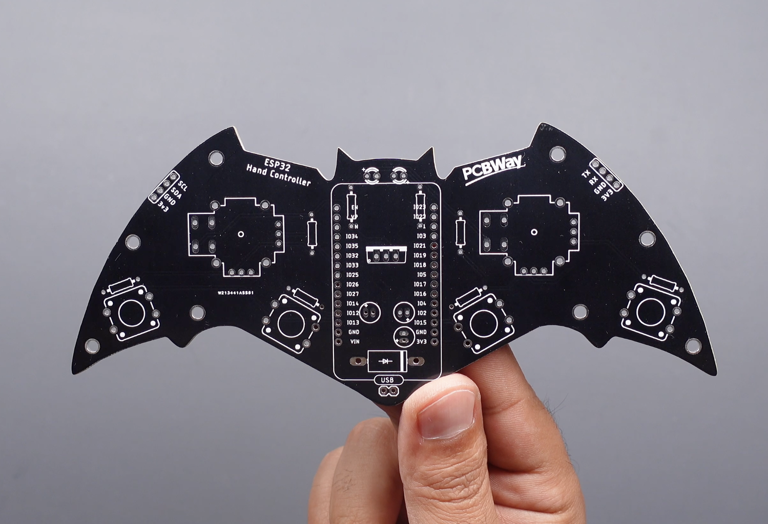
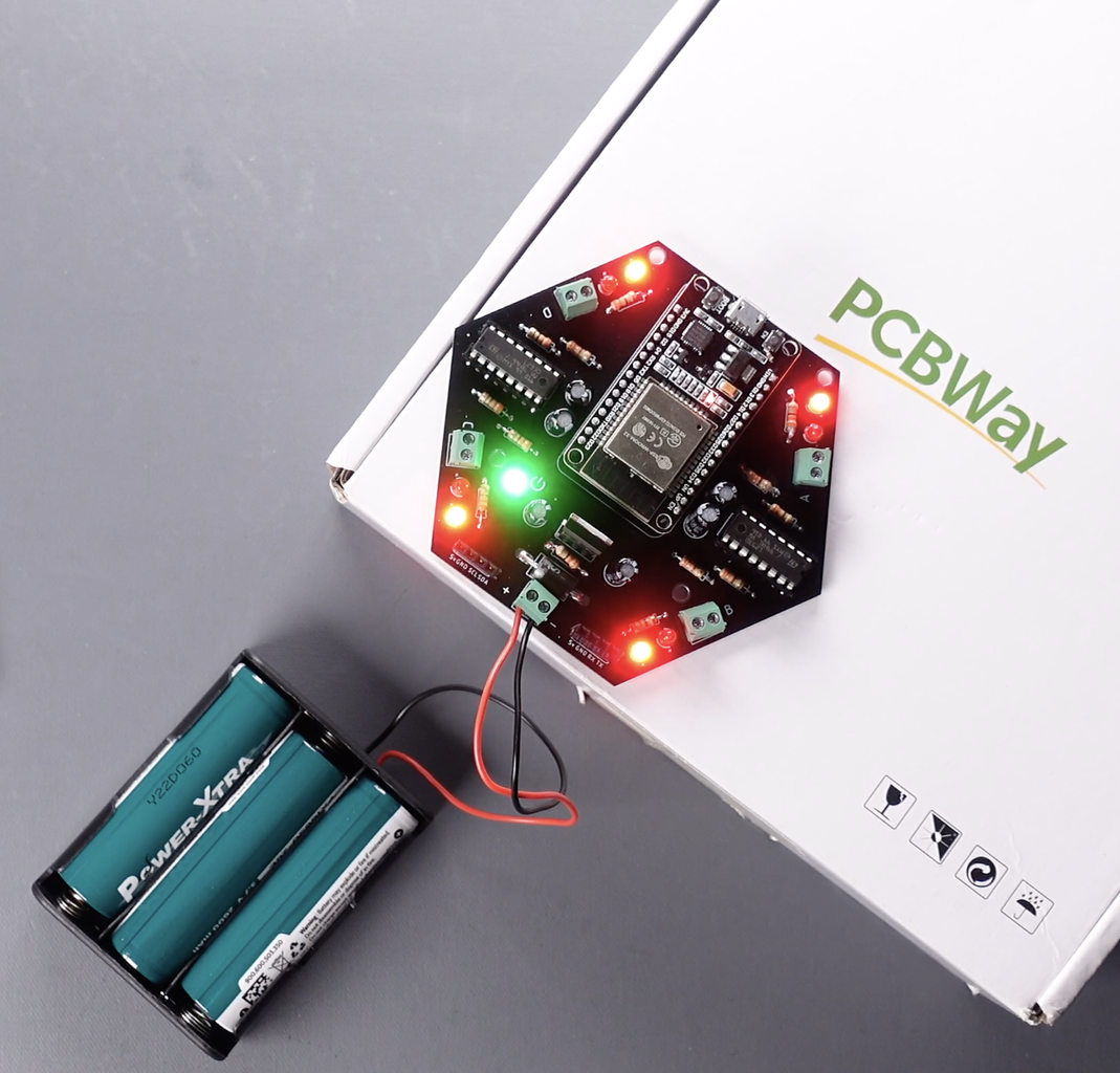
I preferred a bat theme while designing the PCB to have a unique design. I also preferred the ESP32 board, which many of us have heard of, but have some worries about using. In fact, the ESP32 board is more efficient than other boards in terms of communication options. Because an ESP32 board allows Bluetooth, Wi-Fi, MAC address and more wireless communication ways. I also think that it is sufficient on the number of pins compared to other boards. Finally, an ESP32 board is pretty easy to use...
Thank you PCBWay for support and sponsorship in ordering the printed circuit board. For high-quality PCBs, you can choose PCBWay. If you want to get this printed circuit board easily, you can download the PCB Gerber file from the link below or order it directly.
pcbway.com/project/shareproject/Bat_Hand_Controller_ESP32_and_Joystick.html
Step 3: Components and Soldering


If you look at the bill of material (BOM), easily solderable components were preferred, so you can easily assembly your printed circuit board by following the circuit diagram designator.
You need few components for the printed circuit board:
- 1x Diode SB560
- 3x Capacitor 100uf 25V
- 2x Thumb Joystick
- 1x Regulator 7805CV
- 2x LED 3mm
- 2x Resistor 330R
- 6x Resistor 4.7K
- 1x ESP32 Devkit V1
- 2x Female Header 1x4 2.54
- 1x Connector 1x2
- 4x Momentary Switch 12mm
Step 4: Breadboard Circuit


For those who want to experience communicating from ESP32 to ESP32 using ESP-NOW before ordering the printed circuit board, I built two breadboard circuits as sender and receiver. You can build your circuit and test the source code by following the shared circuit diagram.
Step 5: Getting Board MAC Address

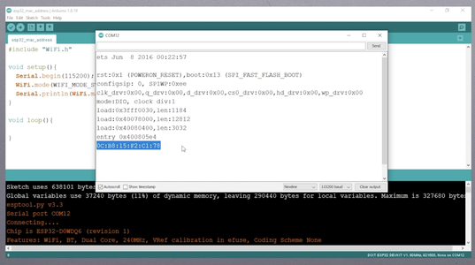
To communicate via ESP-NOW, you need to know the MAC Address of the ESP32 receiver. To get your board’s MAC Address, upload the shared following code. That’s how you know to which device you’ll send the data to. Each ESP32 has a unique MAC Address and this is used to send data using ESP-NOW.
After uploading the code, open the Serial Monitor at a baud rate of 115200 and press the ESP32 RST/EN button. The MAC address should be printed. Save your board MAC address because you’ll need it to send data to the right board. If you want to establish two-way communication between both boards, you will also need the MAC address of the second board.
Attachments

Step 6: One-way Point to Point Communication


Let's examine the button-to-motor source code created for the breadboard circuit to simply explain the operation of the source code and ESP-NOW. The circuit to which the button is connected uses the 'Sender' code, while the circuit to which the motor is connected uses the 'Receiver' code.
Once you understand the working principle of these simple codes, you can more easily edit the source code created for Joystick Hand Controller and L293D Motor Board.
Open the shared source code for the Sender-ESP32-Button
- The GPIO pin that the "button" is connected to is defined in the code. Then a variable is defined to read the "button state".
- Next, the MAC address of the receiver-board is entered.
- Then, create a structure that contains the type of data we want to send. Called this structure "struct_message" and it contain an integer variable type (int buttonValue). You can change this to send other types of variables (like char, float, bool).
- When the button is pressed, the value of the button is read and the button state is determined. The button state is sent with the message structure as the button value.
Open the shared source code for the Receiver-ESP32-Motor
- Define the GPIO pin that the "motor" is connected
- Define the message structure to be received from the sender. Must match the sender structure.
- Define a variable for motor state.
- The button value read from the sender is written to the motor state variable, and the motor state variable controls the pin of the motor.
Upload the sender and receiver source codes. Then test it and see how it works. If all is well, you can edit and use the source codes created and shared for Joystick Hand Controller and L293D Motor Driver board.
Step 7: L293D Motor Driver Board
If you need more details about the L293D Motor Driver board, check out the Instructables page here:
https://www.instructables.com/ESP32-Mecanum-Wheels-Robot-and-Bluetooth-Gamepad/
In this article, you can find the installation of the mecanum wheels robot and the build and use of the L293D Motor Driver board.
If you have any ideas, please let them know in the comment section. Follow to be informed about the next projects.
Participated in the
Remote Control Contest


