

Introduction: ESP32 Servo Motor Controller Board - Wireless Control With Bluetooth App and ESP32 to ESP32
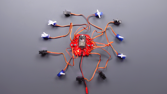


In this project we will look at the assembly and use of ESP32 based printed circuit board that allows you to control up to 16 servo motors. The ESP32 board provides various communication options and methods this allows you to communicate wirelessly with other hardware. Watch the video to see how it works...
Step 1: How It Works?
As seen in the video, I control multiple servo motors wirelessly both with the joystick and with my smartphone. Communication was achieved via both MAC address and Bluetooth. If you want, you can also use WiFi, another communication method of ESP32. ESP-NOW method was used for MAC address communication. Thus, you can communicate two ESP32 boards, one-way and two-way. Bluetooth, which is also built into the ESP32 board, was used for application communication.
Step 2: Required Components

Let's take a look at what is required for the ESP32 servo motor controller board. The preferred components are those that are mostly used in basic electronics and that can be easily assembled.
- 100uF 25V~6V Capacitor
- 470uF 25V~6V Capacitor
- SB560 Diode
- 7805CV Voltage Regulator
- 3mm LED
- 330Ohm Resistor
- 2 Pin 5mm Screw Terminal
- ESP32 Devkit V1
- Male and Female Headers
Step 3: Printed Circuit Board
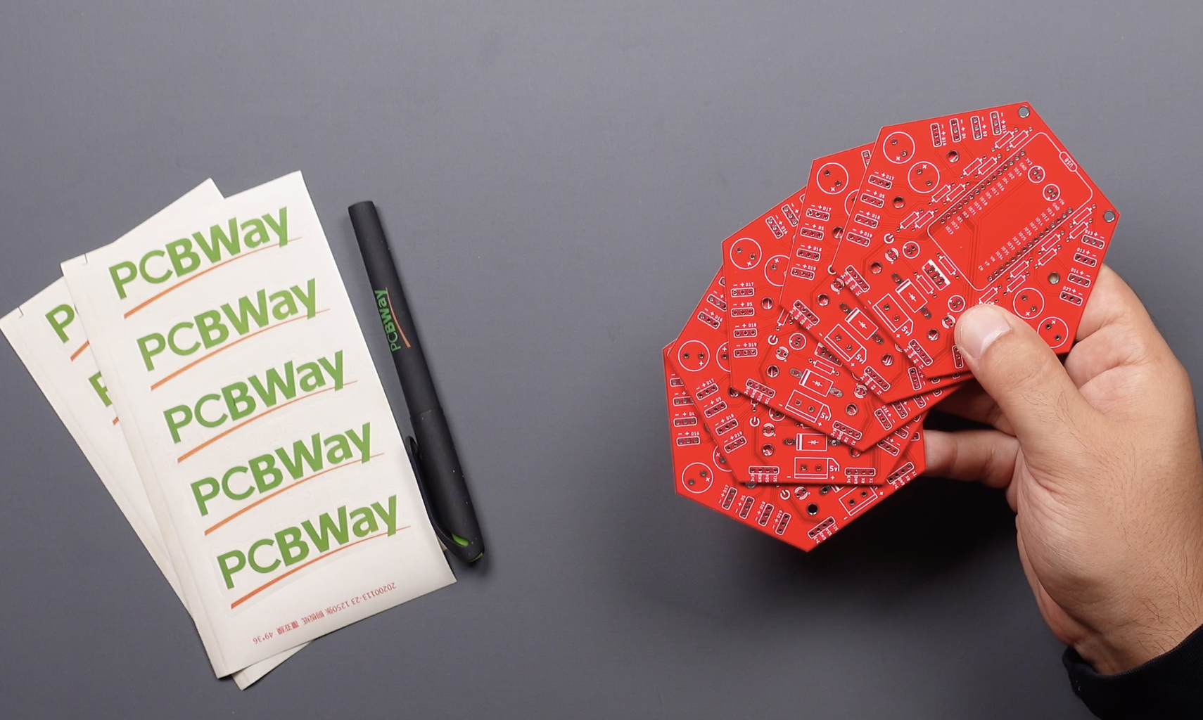


Of course we need a printed circuit board on which to assemble these components. If we take a closer look at the design it has a hexagonal shape and has 16 servo motor connection ports. It is possible to use input and output pins for different projects other than servo motor control. I'm preferring PCBWay for printed circuit board service. It's pretty easy to order you can upload the shared Gerber file to pcbway.com and create an order easily... Cheap and high-quality PCBs will be delivered in a few days depending on your address.
Step 4: Soldering
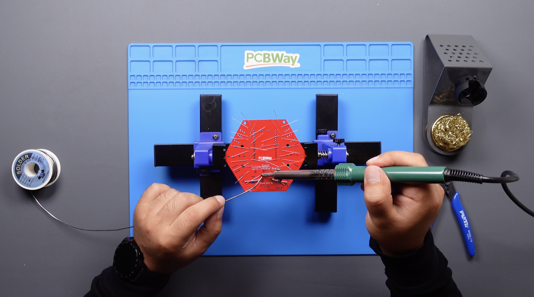
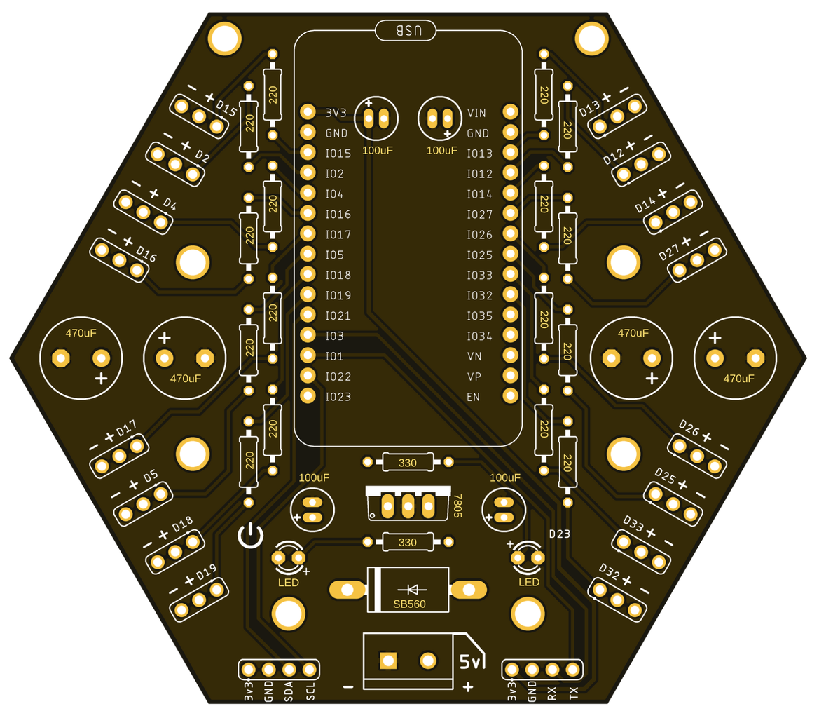


If you look at the bill of material (BOM), easily solderable components were preferred, so you can easily assembly your printed circuit board by following the circuit diagram designator.
You need few tools for the soldering:
- Soldering Iron
- Solder Wire
- Soldering Clamp Holder
Step 5: ESP32 Setup for Arduino IDE
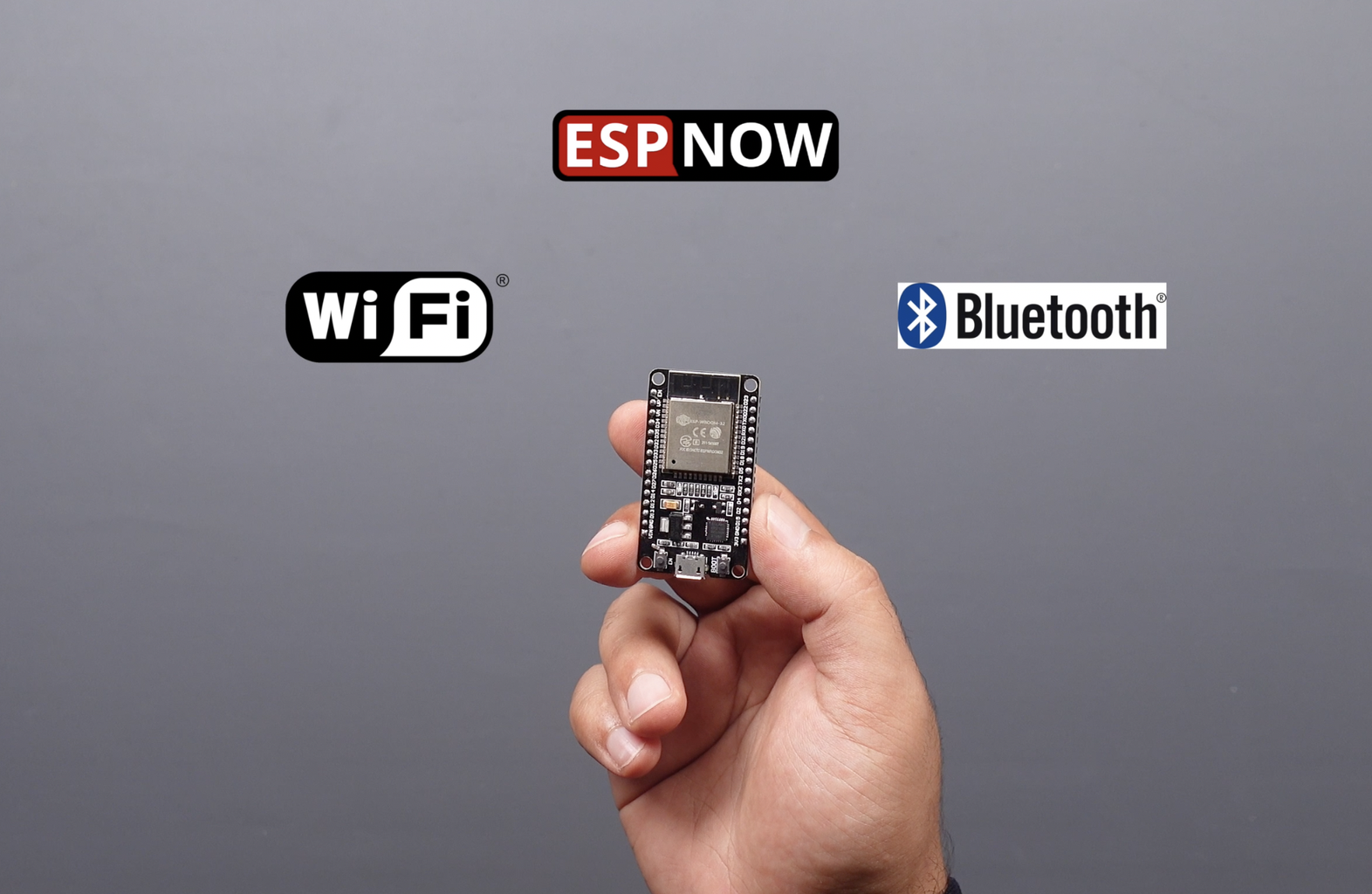


I used the ESP32 development board, which provides two different connection methods (WiFi & Bluetooth) to control the robot wirelessly. ESP32 is a microcontroller has builtin Wifi and dual mode Bluetooth support. It can be programmed through various programming platforms like Arduino IDE. For programming ESP32 board with Arduino IDE first step is to add ESP32 board support on Arduino IDE. For this follow the steps below:
- Open Arduino IDE go to “File” in menu bar and open “Preferences”.
- As “Preferences” dialog box opens, copy the URL in “Additional Board Manager URLs” box highlighted in image below.After this select “OK”. URL https://dl.espressif.com/dl/package_esp32_index.json
- Now go to “Tools>Board>Board Manager”.
- Search the “esp32”, you can see the esp32 package by Espressif Systems in Board Manager select it and then select “Install”.
Step 6: Source Code (Self-moving)


Let's take a look at the source code created for a simple servo motor control in this section. Let's test our board by providing eleven servo motors in a cycle from 180 degrees to 0 degrees and vice versa.
#include <Servo.h>

static const int servo1Pin = 13;
static const int servo2Pin = 14;
static const int servo3Pin = 26;
static const int servo4Pin = 33;
static const int servo5Pin = 18;
static const int servo6Pin = 17;
static const int servo7Pin = 4;
static const int servo8Pin = 15;
static const int servo9Pin = 16;
static const int servo10Pin = 32;
static const int servo11Pin = 27;

Servo servo1;
Servo servo2;
Servo servo3;
Servo servo4;
Servo servo5;
Servo servo6;
Servo servo7;
Servo servo8;
Servo servo9;
Servo servo10;
Servo servo11;


void setup() {
    Serial.begin(115200);
    servo1.attach(servo1Pin);
    servo2.attach(servo2Pin);
    servo3.attach(servo3Pin);
    servo4.attach(servo4Pin);
    servo5.attach(servo5Pin);
    servo6.attach(servo6Pin);
    servo7.attach(servo7Pin);
    servo8.attach(servo8Pin);
    servo9.attach(servo9Pin);
    servo10.attach(servo10Pin);
    servo11.attach(servo11Pin);
    delay(3000);
}


void loop() {
    for(int posDegrees = 0; posDegrees <= 180; posDegrees++) {
        servo1.write(posDegrees);
        servo2.write(posDegrees);
        servo3.write(posDegrees);
        servo4.write(posDegrees);
        servo5.write(posDegrees);
        servo6.write(posDegrees);
        servo7.write(posDegrees);
        servo8.write(posDegrees);
        servo9.write(posDegrees);
        servo10.write(posDegrees);
        servo11.write(posDegrees);
        Serial.println(posDegrees);
        delay(10);
    }


    for(int posDegrees = 180; posDegrees >= 0; posDegrees--) {
        servo1.write(posDegrees);
        servo2.write(posDegrees);
        servo3.write(posDegrees);
        servo4.write(posDegrees);
        servo5.write(posDegrees);
        servo6.write(posDegrees);
        servo7.write(posDegrees);
        servo8.write(posDegrees);
        servo9.write(posDegrees);
        servo10.write(posDegrees);
        servo11.write(posDegrees);
        Serial.println(posDegrees);
        delay(10);
    }
}
Consider the power required for the type of servo motor used when operating the board. Servo motors are externally connected directly to the power supply from the ESP32 board. A voltage regulator (L7805) is used for the ESP32 and the minimum power supply rating should be 5V~6V.
The board was able to move eleven hobby servo motors simultaneously. Let's try moving a robotic arm in the next step.
#include <Servo.h>

static const int servo1Pin = 13;
static const int servo2Pin = 16;
static const int servo3Pin = 27;

#define LEDpin 23

Servo servo1;
Servo servo2;
Servo servo3;

void setup() {
    Serial.begin(115200);
    servo1.attach(servo1Pin);
    servo2.attach(servo2Pin);
    servo3.attach(servo3Pin);
    pinMode(LEDpin, OUTPUT);
    delay(3000);
}

void loop() {
    for(int posDegrees = 90; posDegrees <= 120; posDegrees++) {
        servo1.write(posDegrees);
        digitalWrite(LEDpin, HIGH);
        Serial.println(posDegrees);
        delay(20);
    }
    delay(100);
    for(int posDegrees = 120; posDegrees >= 90; posDegrees--) {
        servo1.write(posDegrees);
        Serial.println(posDegrees);
        digitalWrite(LEDpin, LOW);
        delay(20);
    }
    delay(100);
    for(int posDegrees = 90; posDegrees >= 60; posDegrees--) {
        servo1.write(posDegrees);
        Serial.println(posDegrees);
        digitalWrite(LEDpin, HIGH);
        delay(20);
    }
    delay(100);
    for(int posDegrees = 60; posDegrees <= 90; posDegrees++) {
        servo1.write(posDegrees);
        Serial.println(posDegrees);
        digitalWrite(LEDpin, LOW);
        delay(20);
    }
    delay(100);
    for(int posDegrees = 100; posDegrees <= 150; posDegrees++) {
        servo2.write(posDegrees);
        digitalWrite(LEDpin, HIGH);
        Serial.println(posDegrees);
        delay(20);
    }
    delay(100);
    for(int posDegrees = 150; posDegrees >= 100; posDegrees--) {
        servo2.write(posDegrees);
        digitalWrite(LEDpin, LOW);
        Serial.println(posDegrees);
        delay(20);
    }
    delay(100);
    for(int posDegrees = 80; posDegrees <= 130; posDegrees++) {
        servo3.write(posDegrees);
        digitalWrite(LEDpin, HIGH);
        Serial.println(posDegrees);
        delay(20);
    }
    delay(100);
    for(int posDegrees = 130; posDegrees >= 80; posDegrees--) {
        servo3.write(posDegrees);
        digitalWrite(LEDpin, LOW);
        Serial.println(posDegrees);
        delay(20);
    }
    delay(2000);
}
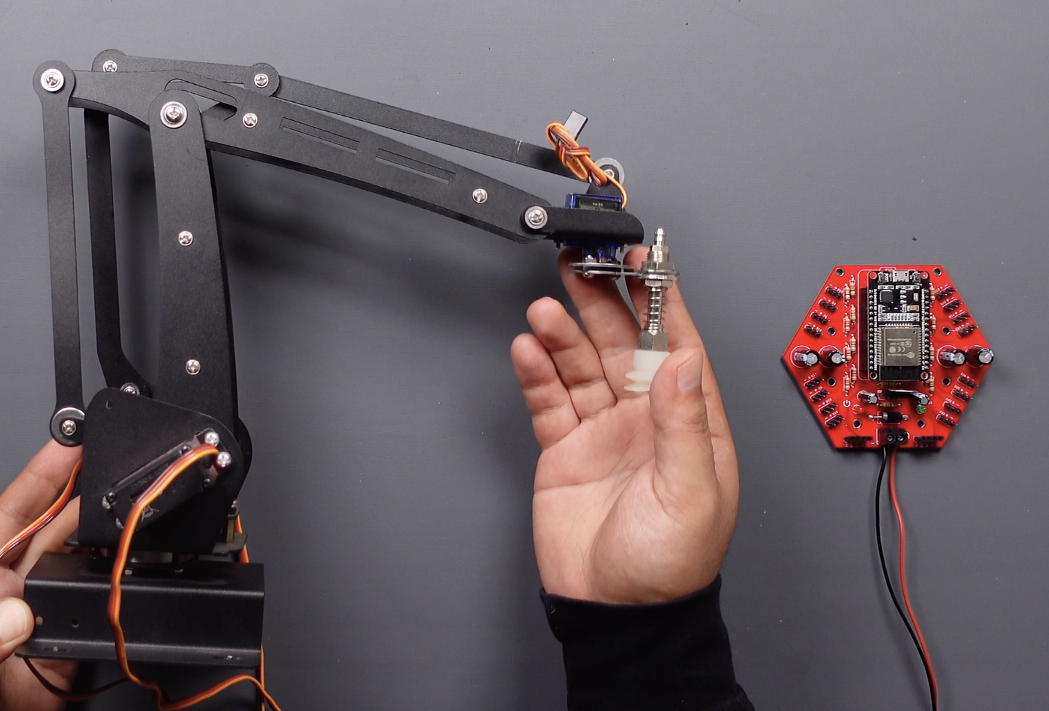
In this code, we will again provide self-move. Let's move the servo motors at the specified angles using the "for loop". This time I will supply the 6.6 volts needed by the robotic arm motors to the board. The board has successfully moved the high-torque robotic arm servo motors... In the next section, we will move it wirelessly using an app via bluetooth.
Step 7: Source Code (Smartphone App Via Bluetooth)


In this section we will use a smartphone application. I needed a smartphone application to wirelessly control motors via bluetooth, and I discovered an application. This is an application developed by STEMpedia that you can use for free on Android and iOS devices.
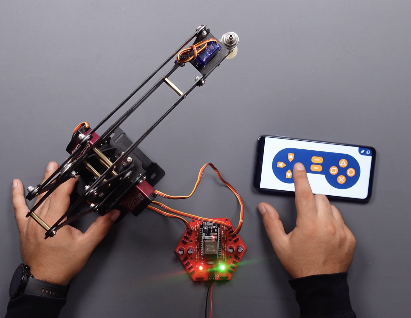
In this project I chose the digital mode, this way I have a hand controller with many buttons to move the robotic arm in many directions. The digital mode is the default mode when the gamepad is turned on. Let's move the servo motors at the defined angle when the buttons in the gamepad mode are pressed.
Using Gamepad module with ESP32:
- First download library Dabble-ESP32: https://thestempedia.com/download/24469/
- Add the downloaded zip file of the library to Arduino IDE. Navigate to “Sketch>>Include Library >>Add .ZIP Library” in Menu Bar.
- After successfully installing library open the shared source code.
#define CUSTOM_SETTINGS
#define INCLUDE_GAMEPAD_MODULE
#include <DabbleESP32.h>
#include <Arduino.h>
#include <Servo.h>

//create servo object to control a servo
Servo leftRight;
Servo upDown;
Servo backForth;

#define leftRightPin 13
#define upDownPin 12
#define backForthPin 15
#define LEDpin 23

//initial angle  for servo
int angle = 90;
int angleStep = 1;

void setup() {
  leftRight.attach(leftRightPin);
  upDown.attach(upDownPin);
  backForth.attach(backForthPin);
  pinMode(LEDpin, OUTPUT);
  Serial.begin(115200);
  Dabble.begin("ESP32ServoController");
}

void loop() {
  Dabble.processInput();
  if (GamePad.isLeftPressed()) {
    angle = angle + angleStep;
    leftRight.write(angle);
    digitalWrite(LEDpin, HIGH);
    delay(20);
  }
  else if (GamePad.isRightPressed()) {
    angle = angle - angleStep;
    leftRight.write(angle);
    digitalWrite(LEDpin, HIGH);
    delay(20);
  }
  else if (GamePad.isUpPressed()) {
    angle = angle - angleStep;
    upDown.write(angle);
    digitalWrite(LEDpin, HIGH);
    delay(20);
  }
  else if (GamePad.isDownPressed()) {
    angle = angle + angleStep;
    upDown.write(angle);
    digitalWrite(LEDpin, HIGH);
    delay(20);
  }
  else if (GamePad.isTrianglePressed()) {
    angle = angle + angleStep;
    backForth.write(angle);
    digitalWrite(LEDpin, HIGH);
    delay(20);
  }
  else if (GamePad.isCrossPressed()) {
    angle = angle - angleStep;
    backForth.write(angle);
    digitalWrite(LEDpin, HIGH);
    delay(20);
  }
  else if (GamePad.isStartPressed()) {
    leftRight.write(angle);
    delay(500);
    upDown.write(angle);
    delay(500);
    backForth.write(angle);
    delay(500);
    digitalWrite(LEDpin, HIGH);
    delay(100);
    digitalWrite(LEDpin, LOW);
    delay(100);
    digitalWrite(LEDpin, HIGH);
    delay(100);
    digitalWrite(LEDpin, LOW);
    delay(100);
    digitalWrite(LEDpin, HIGH);
    delay(100);
    digitalWrite(LEDpin, LOW);
  }
  else {
    digitalWrite(LEDpin, LOW);
  }
}
The servo motor names to which the robotic arm are connected are defined, the only change to be made here is the pin numbers. Please update this section if you have used different pins other than the pins specified in the schematic.
//create servo object to control a servo
Servo leftRight;
Servo upDown;
Servo backForth;

#define leftRightPin 13
#define upDownPin 12
#define backForthPin 15
#define LEDpin 23
Digital mode has 10 digital buttons whose data is sent to the device when they are pressed or released. These buttons are defined in the code as follows: Up, Down, Right, Left, Triangle, Circle, Cross, Square, Select, and Start
void loop() {
  Dabble.processInput();
  if (GamePad.isLeftPressed()) {
    angle = angle + angleStep;
    leftRight.write(angle);
    digitalWrite(LEDpin, HIGH);
    delay(20);
  }
  else if (GamePad.isRightPressed()) {
    angle = angle - angleStep;
    leftRight.write(angle);
    digitalWrite(LEDpin, HIGH);
    delay(20);
  }
  else if (GamePad.isUpPressed()) {
    angle = angle - angleStep;
    upDown.write(angle);
    digitalWrite(LEDpin, HIGH);
    delay(20);
  }
  else if (GamePad.isDownPressed()) {
    angle = angle + angleStep;
    upDown.write(angle);
    digitalWrite(LEDpin, HIGH);
    delay(20);
  }
  else if (GamePad.isTrianglePressed()) {
    angle = angle + angleStep;
    backForth.write(angle);
    digitalWrite(LEDpin, HIGH);
    delay(20);
  }
  else if (GamePad.isCrossPressed()) {
    angle = angle - angleStep;
    backForth.write(angle);
    digitalWrite(LEDpin, HIGH);
    delay(20);
When any gamepad button is pressed, the function you want is executed. The board successfully established bluetooth and smartphone communication... In the next and last section, let's communicate by providing one-way communication between two ESP32 boards.
I shared a more detailed project for controlling ESP32 with smartphone app, check it out! https://www.instructables.com/ESP32-Mecanum-Wheels-Robot-and-Bluetooth-Gamepad
Step 8: Source Code (ESP32 to ESP32 Communication)
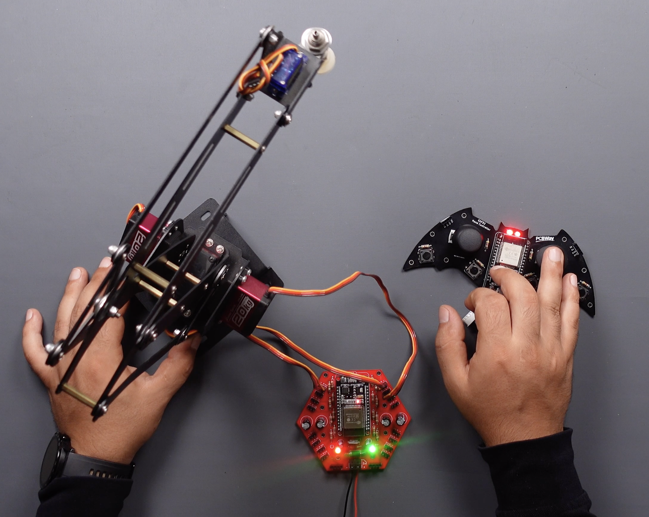


In this section, I will use the ESP32 hand-controller that was shared before (https://www.instructables.com/ESP32-Joystick-Hand-Controller-ESP-NOW), we will communicate with two ESP32 via the MAC address using the ESP-NOW method. We need two ESP32 as receiver and transmitter. First, upload the code to find the MAC address of the receiver and view and save the MAC address with the serial monitor.
#include "WiFi.h"

void setup(){
  Serial.begin(115200);
  WiFi.mode(WIFI_MODE_STA);
  Serial.println(WiFi.macAddress());
}

void loop(){


}
Then open the receiver code created for the servo motor controller board, update it as you want and upload.
#include <esp_now.h>
#include <WiFi.h>
#include <Servo.h>

//create servo object to control a servo
Servo leftRight;
Servo upDown;
Servo backForth;

#define leftRightPin 13
#define upDownPin 12
#define backForthPin 15
#define LEDpin 23

//initial angle  for servo
int angle = 90;
int angleStep = 1;

// Structure example to receive data
// Must match the sender structure
typedef struct struct_message {
  int rightJoyXvalue;
  int rightJoyYvalue;
  int rightJoySWvalue;
  int rightButtonAvalue;
  int rightButtonBvalue;
  int leftJoyXvalue;
  int leftJoyYvalue;
  int leftJoySWvalue;
  int leftButtonAvalue;
  int leftButtonBvalue;
} struct_message;


// Create a struct_message called myData
struct_message readingData;


// callback function that will be executed when data is received
void OnDataRecv(const uint8_t * mac, const uint8_t *incomingData, int len) {
  memcpy(&readingData, incomingData, sizeof(readingData));
  //Serial.print("Bytes received: ");
  //Serial.println(len);


  if (readingData.rightJoyXvalue == HIGH) {
    Serial.print("Right Joy X : ");
    Serial.println(readingData.rightJoyXvalue);
    Serial.println();
    angle = angle + angleStep;
    leftRight.write(angle);
    digitalWrite(LEDpin, HIGH);
    delay(20);
  }
  else if (readingData.leftJoyXvalue == HIGH) {
    Serial.print("Left Joy X : ");
    Serial.println(readingData.leftJoyXvalue);
    Serial.println();
    angle = angle - angleStep;
    leftRight.write(angle);
    digitalWrite(LEDpin, HIGH);
    delay(20);
  }
  else if (readingData.rightJoyYvalue == LOW) {
    Serial.print("Right Joy Y : ");
    Serial.println(readingData.rightJoyYvalue);
    Serial.println();
    angle = angle + angleStep;
    upDown.write(angle);
    digitalWrite(LEDpin, HIGH);
    delay(20);
  }
  else if (readingData.leftJoyYvalue == HIGH) {
    Serial.print("Left Joy Y : ");
    Serial.println(readingData.leftJoyYvalue);
    Serial.println();
    angle = angle - angleStep;
    upDown.write(angle);
    digitalWrite(LEDpin, HIGH);
    delay(20);
  }
  else if (readingData.rightJoySWvalue == LOW) {
    Serial.print("Right Joy SW : ");
    Serial.println(readingData.rightJoySWvalue);
    Serial.println();
    angle = angle + angleStep;
    backForth.write(angle);
    digitalWrite(LEDpin, HIGH);
    delay(20);
  }
  else if (readingData.leftJoySWvalue == LOW) {
    Serial.print("Left Joy SW : ");
    Serial.println(readingData.leftJoySWvalue);
    Serial.println();
    angle = angle - angleStep;
    backForth.write(angle);
    digitalWrite(LEDpin, HIGH);
    delay(20);
  }
  else {
    digitalWrite(LEDpin, LOW);
  }
}


void setup() {
  // Initialize Serial Monitor
  Serial.begin(115200);


  leftRight.attach(leftRightPin);
  upDown.attach(upDownPin);
  backForth.attach(backForthPin);
  pinMode(LEDpin, OUTPUT);


  // Set device as a Wi-Fi Station
  WiFi.mode(WIFI_STA);


  // Init ESP-NOW
  if (esp_now_init() != ESP_OK) {
    Serial.println("Error initializing ESP-NOW");
    return;
  }


  // Once ESPNow is successfully Init, we will register for recv CB to
  // get recv packer info
  esp_now_register_recv_cb(OnDataRecv);
}


void loop() {


}
Finally, open the shared code for the transmitter and update the MAC address of the receiver, then upload the transmitter code after making the desired changes.
#include <esp_now.h>
#include <WiFi.h>


#define rightJoyX     32
#define rightJoyY     35
#define rightJoySW    26
#define rightButtonA  2
#define rightButtonB  15


#define leftJoyX      34
#define leftJoyY      33
#define leftJoySW     25
#define leftButtonA   13
#define leftButtonB   12


#define LEDpin        23


int rightJoyXstate;
int rightJoyYstate;
int rightJoySWstate;
int rightButtonAstate;
int rightButtonBstate;
int leftJoyXstate;
int leftJoyYstate;
int leftJoySWstate;
int leftButtonAstate;
int leftButtonBstate;


// REPLACE WITH YOUR RECEIVER MAC Address
uint8_t broadcastAddress[] = {0x0C, 0xB8, 0x15, 0xC4, 0x82, 0x2C};


// Structure example to send data
// Must match the receiver structure
typedef struct struct_message {
  int rightJoyXvalue;
  int rightJoyYvalue;
  int rightJoySWvalue;
  int rightButtonAvalue;
  int rightButtonBvalue;
  int leftJoyXvalue;
  int leftJoyYvalue;
  int leftJoySWvalue;
  int leftButtonAvalue;
  int leftButtonBvalue;
} struct_message;


// Create a struct_message called myData
struct_message handControllerData;


esp_now_peer_info_t peerInfo;


// callback when data is sent
void OnDataSent(const uint8_t *mac_addr, esp_now_send_status_t status) {
  Serial.print("\r\nLast Packet Send Status:\t");
  Serial.println(status == ESP_NOW_SEND_SUCCESS ? "Delivery Success" : "Delivery Fail");
}


void setup() {
  // Init Serial Monitor
  Serial.begin(115200);
  pinMode(rightJoyX, INPUT);
  pinMode(rightJoyY, INPUT);
  pinMode(rightJoySW, INPUT);
  pinMode(rightButtonA, INPUT);
  pinMode(rightButtonB, INPUT);
  pinMode(leftJoyX, INPUT);
  pinMode(leftJoyY, INPUT);
  pinMode(leftJoySW, INPUT);
  pinMode(leftButtonA, INPUT);
  pinMode(leftButtonB, INPUT);
  pinMode(LEDpin, OUTPUT);


  digitalWrite(LEDpin, HIGH);


  // Set device as a Wi-Fi Station
  WiFi.mode(WIFI_STA);


  // Init ESP-NOW
  if (esp_now_init() != ESP_OK) {
    Serial.println("Error initializing ESP-NOW");
    return;
  }


  // Once ESPNow is successfully Init, we will register for Send CB to
  // get the status of Trasnmitted packet
  esp_now_register_send_cb(OnDataSent);


  // Register peer
  memcpy(peerInfo.peer_addr, broadcastAddress, 6);
  peerInfo.channel = 0;
  peerInfo.encrypt = false;


  // Add peer
  if (esp_now_add_peer(&peerInfo) != ESP_OK) {
    Serial.println("Failed to add peer");
    return;
  }
}


void loop() {
  // Set values to send
  rightJoyXstate = digitalRead(rightJoyX);
  handControllerData.rightJoyXvalue = rightJoyXstate;
  rightJoyYstate = digitalRead(rightJoyY);
  handControllerData.rightJoyYvalue = rightJoyYstate;
  rightJoySWstate = digitalRead(rightJoySW);
  handControllerData.rightJoySWvalue = rightJoySWstate;
  Serial.print("rightJoySWstate :");
  Serial.println(rightJoySWstate);
  rightButtonAstate = digitalRead(rightButtonA);
  handControllerData.rightButtonAvalue = rightButtonAstate;
  rightButtonBstate = digitalRead(rightButtonB);
  handControllerData.rightButtonBvalue = rightButtonBstate;


  leftJoyXstate = digitalRead(leftJoyX);
  handControllerData.leftJoyXvalue = leftJoyXstate;
  leftJoyYstate = digitalRead(leftJoyY);
  handControllerData.leftJoyYvalue = leftJoyYstate;
  leftJoySWstate = digitalRead(leftJoySW);
  handControllerData.leftJoySWvalue = leftJoySWstate;
  leftButtonAstate = digitalRead(leftButtonA);
  handControllerData.leftButtonAvalue = leftButtonAstate;
  leftButtonBstate = digitalRead(leftButtonB);
  handControllerData.leftButtonBvalue = leftButtonBstate;


  // Send message via ESP-NOW
  esp_err_t result = esp_now_send(broadcastAddress, (uint8_t *) &handControllerData, sizeof(handControllerData));


  if (result == ESP_OK) {
    Serial.println("Sent with success");
  }
  else {
    Serial.println("Error sending the data");
  }
  delay(50);
}
The board successfully communicated between the two ESP32s and successfully moved the robotic arm servo motors. Thanks for reading or watching my project. If you have any ideas, please let me know in the comment section. Follow to be informed about the next projects.

Participated in the
Microcontroller Contest


