

Introduction: ESP8266 Firmware Upgrade or Flashing


After a year or so of experimenting with Arduino I wanted to take it to the next level ie. connecting to the internet. Very quickly I came across the ESP8266 module. Some experimenting with an ESP8266 using the Arduino IDE left me with too much a feeling of handling some black box. As soon as I wanted to change the operation of the ESP8266 I ran into a wall. No way to change operating parameters such as baud rate, deep sleep, etc..
For example, in the projects I want to use the ESP8266 I need the SoftwareSerial.h library. However, this library is not reliable beyond some 38400 bauds. But the ESP8266 has a fixed baudrate of 115200 (using the more recent firmwares; the originals, years ago, would make the ESP8266 transmit at 9600 baud). In effect restricting me to use the hardware serial port. But if you work with a Pro Mini, or Uno, then you only have one hardware port; and I needed the hardware port to interface with other peripherals.
So started my quest (because that was what it was) to find ways of altering this "black box" functioning.
Honestly, I did sweat several days and nights through countless fora, websites, blogs, .. Numerous "recipes", often contradicting each other or themselves, often written with the best of intentions, but then only a few webpages did really offer usefull information, at least for my purpose:
1. how does the ESP8266 function
2. how can you change these function parameters
3. what are the pro and contra of the various methods, parameters,..
A very good starter is with a book available for free (although the author asks for a reasonable and well deserved 4 to 5 USD, so if you can afford it: it is money well spent):
Step 1: The Basics


If operating parameters need to be changed, you have to connect to the ESP8622 with a serial connection, using a USB to serial converter. These converters are mostly based on one of these IC's: CH340 (or CH341), CP2102 or FTDI. Each has their own driver to be installed. These little pcb's can be had on Aliexpress for a few $ each. The least problems I had was with the FTDI although the others do well too (just a bit more hassle to install the drivers). When you buy one of these make sure they offer the option to drive either 3V or 5V output.
One important comment: NEVER apply more then 3.3V to Vcc. Two exceptions:
1. when using a development board (ie Node MCU) with an onboard USB connector then you can connect this board directly to USB
2. when applying 3.3V to Vcc you can still safely apply 5V to the IO and TX/RX lines: these are 5V tolerant (this post directly from the boss of Espressif -maker of ESP8266- Teo Swee Ann:
https://www.facebook.com/groups/1499045113679103/permalink/1731855033731442/?hc_location=ufi
This tutorial is made primarily for myself (to remind me of details in a few weeks time when I will have forgotten all how-to's) as well as for anyone else. Since I handle the basics of ESP8266 it does not matter what version is used here:
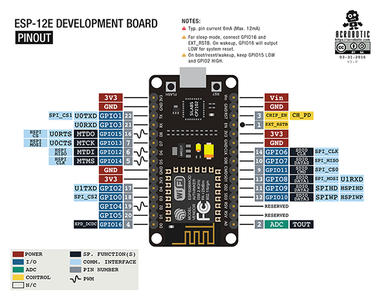
ESP8266 ESP-01, ESP... , ESP12-E, or a development board (which I highly recommend, and for which I would use the Node MCU v1.0 board, available on Aliexpress for less then 3USD).
First things first: get yourself a detailed pin-layout of the specific ESP8266 board you want to use. A few examples are shown in this step.
Know your hardware.
Step 2: Why Flashing? and Tools Needed..
Flashing is needed if you want to change the way the ESP8266 operates. It is impossible to brick the ESP8266 through flashing. If a flashed software does not perform as expected -or performs not at all-: reflash! Keep the flash program parameters at default; except baud rate: first try default, if that does not work try other rates.
Most MCU's have 4M flash size, 40MHz flash speed and use DIO as SPI Mode and 512k+512k memory.
When flashing 4 files are needed (at least if you flash original Espressif flash firmware):
boot_v.x.bin (x to be replaced withwhatever applicable)
esp_init_data_default.bin
userx.1024.new.2.bin (x to be replaced withwhatever applicable)
blank.bin
Each file needs to be flashed in its proper flash memory location; see file in this step.
Tools needed:
1. serial monitor:
A. Putty: http://www.putty.org/
B. TeraTerm: http://tera-term.en.lo4d.com/
C. AccessPort (very good): http://www.sudt.com/en/ap/download.htm
D. Esplorer (java based, but very good): https://esp8266.ru/esplorer/
2. Flashing tools (several tools are available but I found these easiest to install and use):
A. NodeMCUflasher (can be used for any version of ESP8266, not just the Node MCU): https://github.com/nodemcu/nodemcu-flasher
B. Espressif tool flash_download_tools_v3.4.9.2 (make sure you select the ESP8266EX tab): http://www.espressif.com/en/support/download/other-tools

Step 3: Flash Hardware Connections


It is imperative that the correct wiring is used: see added schematics. If you feel safer you can add pull-up resistors for the datalines but keep in mind that the ESP8266 has internal pullup resistors on all IO pins. I included an schematic with pull-up resistors but these are not necessary; the other schematic uses plain connections and works well.
GPIO0 (which is the SPI_CS2 pin) needs to be connected to GND to flash, and needs to be left open (floating) when using the serial monitors or plain when using the chip to interface with anything else.
On the development board there are a RST and FLASH pushbutton, these are not needed when flashing. These can be used in normal operation just to reset the ESP8266 chip.
I use a separate 3.3V supply (MB102 breadboard power supply, less than 2USD on Aliexpress); it is imperative to connect the PSU GND pin to the serial hardware board GND!
Step 4: Download Firmware
Nimerous places offer firmware to download. My beginners' experience taught me to stick to originals from Espressif. You surely can download any fancy firmware written by knowledgeable enthusiasts but either I did things wrong or these firmwares presented all sorts of errors. I am sure a more seasoned programmer will contradict me but hey, this tutorial is written for beginners. Like me.
So, I did get my stuff from http://www.espressif.com/en/products/hardware/esp8266ex/resources (make sure you get the NONOS files, not the RTOS: these are meant for the real pro's) or if you prefer Github: https://github.com/espressif/ESP8266_AT
I downloaded and flashed the 05/05/2017 version (latest at this time), works great. You need to download the source code (zip file), unpack and then choose a boot bin file, take the esp_init_.. file, take a user file from the AT folder, then the 512+512 (this is for 4MB flash sizes; if you are sure you have 8MB then choose the 1024 folder) folder and choose one of both user files.
You can experiment with either of these different files, just make sure you flash four of them as described higher here.
If you happen to drop in on the main Espressif Github page https://github.com/espressif make sure you go to page 2, at the bottom: you need the AT folder. Anything else is free to be experimented with. As I said, you will never be able to brick your ESP8266. For the time being, if you are not a nerd ;).
Step 5: Using the Flash Tools


One step I almost forgot: how to use the flashtools.
Either of the two tools I mentioned above need the following to work:
1. start execution with administrator rights
2. start execution from the folder where you installed the program
3. parameters to be allocated:
A. Crystalfreq: default (26MHz)
B. SPI speed: default (40MHz)
C. SPI mode: default (QIO or DIO)
D. Flash size: default (4Mbit)
E. Comport: the one where your serial adapter is connected to (verify in Device Manager)
F. speed: default, or adjust to 115200, or any other speed where the ESP8266 responds to
4. programs to be loaded:
A. boot.bin first, address 0x00000
B. user1.2014.new.2.bin is next at address 0x01000
C. esp_init_data_default.bin is next at address 0x7C000
D. blank.bin is last at address 0x7E000
EDIT 28/09/2017: when connecting a module for the first time, and no response is received on any baud rate when polling the unit (and after checking thoroughly your wiring!!), give a quick short between RST (or REST) and GND.
This applies as well as for flashing (GPIO0 to GND) as for regular operations (GPIO0 floating).
It also helps to reset after connecting GPIO0 to GND for flashing purposes.
Step 6: AT Commands
Depending on the firmware different AT commands may apply. In the Espressif firmware version 2.1.0 (May 5 2017) with AT version 1.4.0.0 for example the following AT command is used to change the baudrate setting permanently:
AT+UART_DEF=38400,8,1,0,0
..which changes the baudrate to 38400 baud, 8 bits, 1 stop bit, no parity bit, no flowcontrol.
Attachments
Step 7: Where to Find Further Information?
Here are a few links I found to be very useful. Some fora do address the ESP8266 as core business, for example http://www.esp8266.com/viewforum.php?f=160&sid=ab9... (here the first few posts need moderator approval; I found this forum to be not very responsive)
You may try your luck here too (although the my first post is still awaiting moderator approval): http://bbs.espressif.com/
Other, more useful, pages:
https://www.allaboutcircuits.com/projects/update-t...
https://electronics.stackexchange.com/questions/29...
https://nodemcu.readthedocs.io/en/master/en/flash/
This is where I found original Espressif ESP8266 firmware, make sure you download the NONOS firmware, not the RTOS firmware: http://www.espressif.com/en/products/hardware/esp...
Same, but on Github: https://github.com/espressif/ESP8266_NONOS_SDK/tr...
https://www.allaboutcircuits.com/projects/update-t...
http://bbs.espressif.com/viewtopic.php?t=3274
https://alselectro.wordpress.com/2015/05/05/wifi-m...
http://learn.acrobotic.com/tutorials/post/esp8266-...
And about Arduino + ESP8266: http://arduino-esp8266.readthedocs.io/en/latest/e...
Numerous other pages are in my bookmarks, unfortunately I still have to weed out the confusing, contradicting, or plain bad webpages and -sites so this seems like a neverending project. At least my goal is accomplished: how do I change the baudrate in my ESP8266's, while in the process learning how to unfold the black box that Arduino IDE makes it out to be.


