

Introduction: ESP8266 Two Wheel Robot (NodeMCU and Stepper Motor)


Generally, robot cars are built on a chassis with 2 DC motor wheels and a bovine wheel. While surfing the internet, I saw a 3D car design with a different structure, and I wanted to experience it by making it. So take a look at how it works...
Step 1: How It Works?
As you can see the biggest difference compared to other robot cars is that it is built on 2 wheels. Of course, it is possible to make a slight wobble forward and backward from the balance point of view, but this did not hinder the robot's movements.
Also, a NodeMCU board with ESP8266 chip was used instead of an Arduino microcontroller. Thus, the robot was controlled via the internet. Hobby stepper motors were used instead of DC motors. Robot movements have become more balanced with use of stepper motors.
Since we are using ESP8266, it was necessary to move the robot wirelessly over WiFi, and a simple application was made for this.
Step 2: Supplies

Basically, the robot has the necessary equipment such as a microcontroller, two step motors, a motor driver and a battery. The list of required equipment is as follows:
- NodeMCU ESP8266 Board
- 28BYJ-48 Stepper Motors
- ULN2003 Stepper Motor Driver
- 7.4V Li-Po Battery
- Jumper Wires
Additionally you can add an HC-SR04 Ultrasonic Distance Sensor for free movement of the robot.
Step 3: NodeMCU ESP8266 Board


The ESP8266 is a Wi-Fi module great for IoT and Home Automation projects. The ESP8266 is a Wi-Fi module. It allows you to control inputs and outputs as you would do with an Arduino, but it has Wi-Fi.
NodeMCU is an open-source LUA based board developed for the ESP8266 wifi chip. NodeMCU Dev Kit has Arduino like Analog and Digital pins on its board. It supports serial communication protocols i.e. UART, SPI, I2C, etc.
I won't bore you with the details, so you can find more information for the NodeMCU board at this link: https://en.wikipedia.org/wiki/NodeMCU
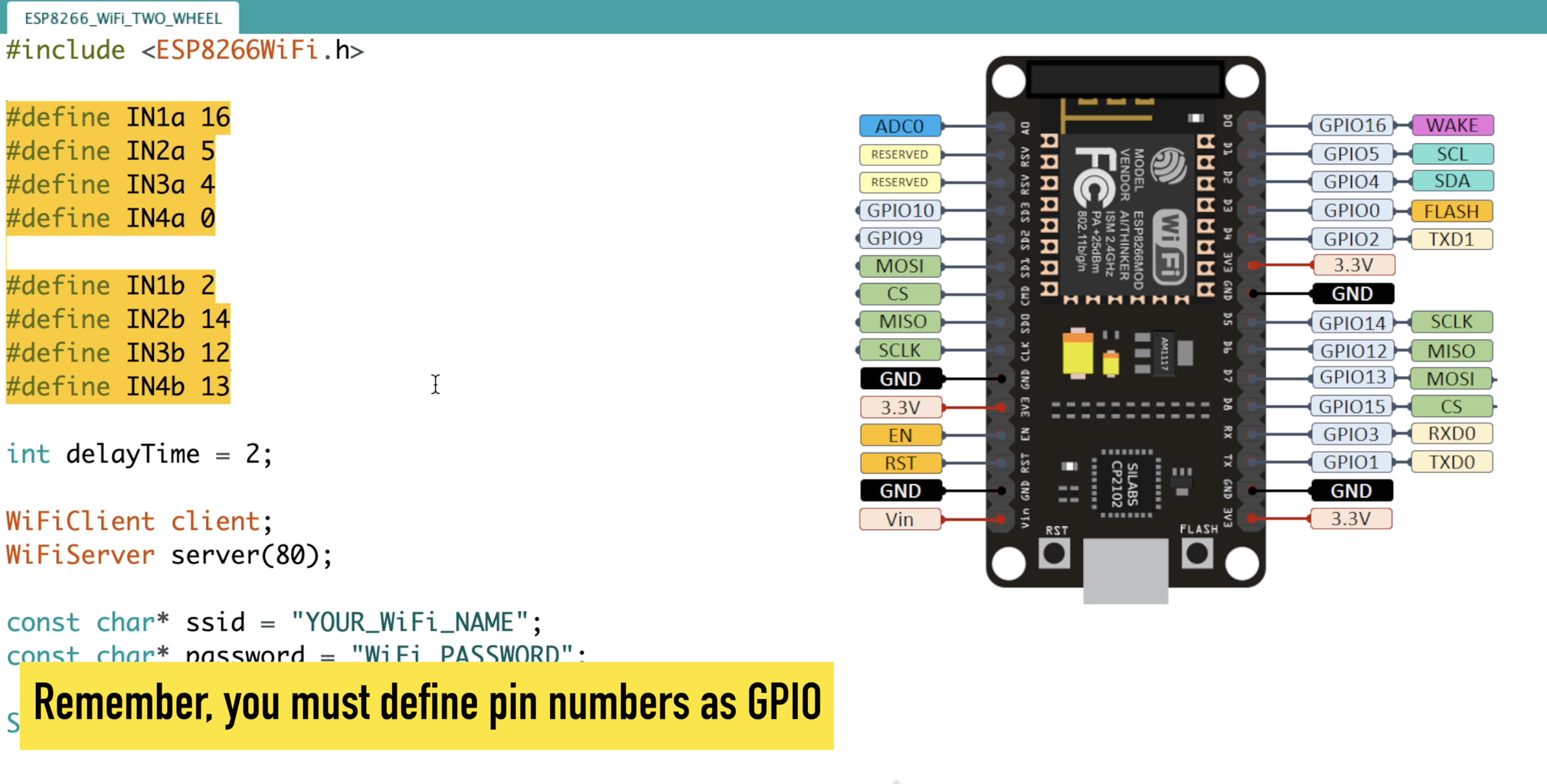
Two things are required when programming NodeMCU and similar cards with ESP8266 chip. First, you will need add-on to programming the ESP8266 with the Arduino IDE. Secondly, when defining the connection pins, you must define them as GPIO.
These stages were mentioned in the source code step.
Step 4: Stepper Motor and Driver

One of the inexpensive way to experience stepper motors is to use 28BYJ-48 stepper motors. One of the best things about these motors is that they can be positioned accurately, one ‘step’ at a time. The other advantage is that they are relatively precise in their movement.
The power consumption of the motor is around 240mA. Because the motor draws too much power, it is best to power it directly from driver rather than drawing that power from the NodeMCU.
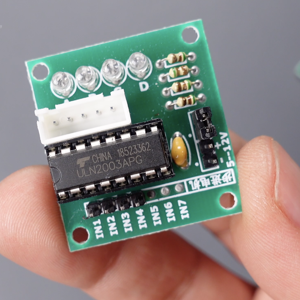
The motor usually come with an ULN2003 based driver board which makes them super easy to use. The ULN2003 is one of the most common motor driver ICs.
The board has a connector that mates the motor wires perfectly which makes it very easy to connect the motor to the board. There are also connections for four control inputs as well as power supply connections.
Step 5: 3D Parts


The 3D models were designed by ftobler and shared on Thingiverse. Download the STL files of the 3D models from the link below and print them with the help of a 3D printer. There is no need for raft and support in 3D printing settings.
Two Wheel 3D Parts - https://www.thingiverse.com/thing:1230244
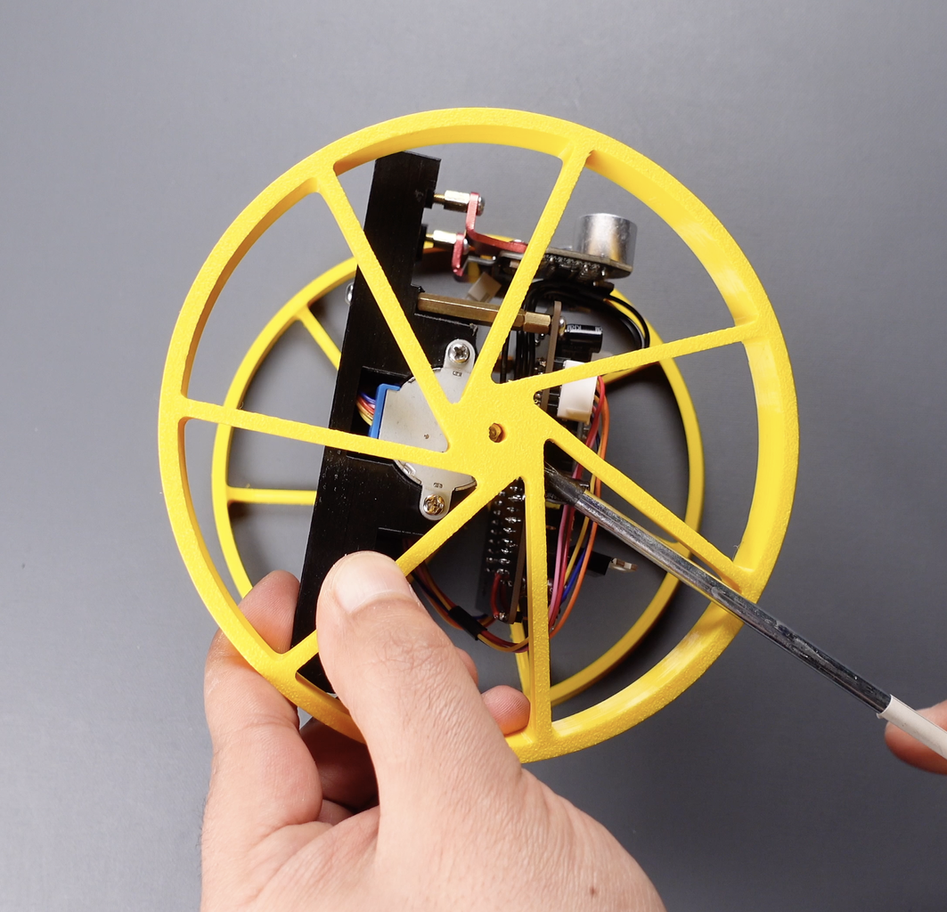
The robot chassis consists of 3 parts, the base on which the motors and circuit are placed and two circle wheels. The assembly is very simple, first of all it is completed by placing the two stepper motors and fixing the wheels to the motors with the help of a screw.
Step 6: Breadboard Circuit


Build your circuit according to the shared circuit diagram. The pin numbers for the connections are as follows.
Motor A Connections
- Driver IN1 to D0 (GPIO16) NodeMCU
- Driver IN2 to D1 (GPIO5) NodeMCU
- Driver IN3 to D2 (GPIO4) NodeMCU
- Driver IN4 to D3 (GPIO0) NodeMCU
- Driver Vin to Power Supply VCC
- Driver GND to Power Supply GND
Motor B Connections
- Driver IN1 to D4 (GPIO2) NodeMCU
- Driver IN2 to D5 (GPIO14) NodeMCU
- Driver IN3 to D6 (GPIO12) NodeMCU
- Driver IN4 to D7 (GPIO13) NodeMCU
- Driver Vin to Power Supply VCC
- Driver GND to Power Supply GND
NodeMCU Power Connections
- NodeMCU Vin to Power Supply VCC
- NodeMCU GND to Power Supply GND
Step 7: Printed Circuit Board (PCB)


After testing the circuit, a PCB was designed to turn the project into a useful prototype. So I cleared the circuit from wiring complexity. To get the PCBs, upload the shared "Gerber" file to PCBWay and create the order. High-quality PCBs will arrive in a few days depending on the shipping address. Place and solder components according to reference designator.
Get the Circuit Diagram and Gerber file: https://www.pcbway.com/project/Two_Wheel_Robot_ESP8266_WiFi.html
Required components for PCB prototype:
- 5x 100uF Capacitor
- 4x 47uF Capacitor
- 1x 330 Resistor
- 1x L7805 Voltage Regulator
- 2x ULN2003 Motor Driver IC
- Female Header
- Male Header
Step 8: Source Code and Application


Let's programming the NodeMCU Board:
- Open the shared source code with the Arduino IDE
- File > Preferences. Enter the ESP8266 URL http://arduino.esp8266.com/stable/package_esp8266com_index.json into the “Additional Boards Manager URLs”
- Go to Tools > Board > Boards Manager. Search the ESP8266 and install
- Go to Tools > Board > Select the NodeMCU 1.0
- Define the pins to which the stepper motors are connected. Remember, you must define pin numbers as GPIO
- Enter your Wifi SSDI and Password
- The data received from the application must match the data in the code... Therefore, the command names specified for robot movements should be defined correctly.
- Displays the local IP address required for communication with the Two Wheel Robot
Create an app to control robot movements via WiFi:
- With the MIT app inventor, an application can be easily developed with the drag-and-drop method
- Import the shared .aia extension resource file after logging in to https://appinventor.mit.edu/ . In this way, you can customize the application according to you.
- The commands to be sent from the application must match the commands specified in the source code
- You can install your app on your phone or tablet with Build > Android app (.apk)
- Enter the local IP address displayed on the serial monitor into the application
- After installing the application, let's test its communication with Two Wheel Robot
Unfortunately, the Instructables does not allow uploading aia files for MIT app inventor. Therefore, you can access the application file from the link below:
https://www.pcbway.com/project/Two_Wheel_Robot_ESP8266_WiFi.html


