

Introduction: ESP8266 WiFi Controlled Aircon Remote


In my first instructableArduino Yun - Solar Panel Monitoring SystemI shared my small project to monitor the production of our solar panels. As we have to be very careful not to produce more energy than we consume, the next logical step is to automatically switch on appliances in the case of energy over-production.
This Instructable is about my small project to automatically switch on the aircon if enough energy is produced by the solar panels.
To achieve this an ESP8266 module is reading the power consumption every minute from the spMonitor device (see above link for details what the spMonitor device does).
If the solar panels produce 100 Watt more than the house is consuming, an aircon is remotely switched on in FAN mode. In this mode my aircon uses around 100W, so the excessive energy is consumed.
If the over-production of energy reaches 500W the aircon is switched from FAN mode to COOL mode to consume the excessive energy.
If the consumption of energy reaches 200W higher than the production of the solar panels the aircon is switched off again.
During a cloudy day the production levels of the solar panels can vary every minute. To avoid repeated on/off switching of the aircon (which is of course not healthy for the appliance) the switching levels must be valid for at least 10 minutes.
The above algorithm is not perfect yet, but I am have it implemented now for more than a week and it works well so far.
All software sources and all schematics are available in my Github repository
WARNING:
I use specific features of the Adafruit HUZZAH ESP8266 module in this instructable. If you plan to build this system with an ESP8266 module from another supplier check carefully that it is compatible with the power supply I use and with the voltage level of the RXD pin. The Adafruit HUZZAH ESP8266 module accepts 3.3V to 12V power supply and has a level shifter on the RXD pin. If your ESP8266 module doesn't have these features you will definitely destroy your module!
Step 1: The Components Used in This Project:


For the remote control:
- Adafruit HUZZAH ESP8266 (or similar ESP12 breakout)
- NPN transistor (I took a S9014, because it was in my storage)
- 330 Ohm resistor
- 2x IR LED e.g. Vishay TSUS4300
To receive the actual energy production value:
- My solar panel monitoring system based on an Arduino Yun
For recording the IR commands from the aircon remote controls:
- Arduino UNO (for recording the IR commands and used as a USBtoSerial converter to program the ESP8266)
- IR receiver (for recording the IR commands). I used a Vishay TSOP58438, but any other IR receiver should work as well.
Beside of the electronics you need of course the environment to program the Arduino Uno and the ESP8266. I use for both the Arduino IDE V1.6.7. The IDE supports natively the Arduino Uno. For the ESP8266 you need to add additional boards with the board manager. Adafruit has a good and easy to understand tutorial how to add support for the ESP8266 to the Arduino IDE: Using Arduino IDE.
Additional libraries needed for the Arduino Uno:
Additional library needed for the ESP8266:
Please use the standard procedures to add these libraries to the Arduino IDE.
All software sources and all schematics are available in my Github repository
WARNING:
I use specific features of the Adafruit HUZZAH ESP8266 module in this instructable. If you plan to build this system with an ESP8266 module from another supplier check carefully that it is compatible with the power supply I use and with the voltage level of the RXD pin. The Adafruit HUZZAH ESP8266 module accepts 3.3V to 12V power supply and has a level shifter on the RXD pin. If your ESP8266 module doesn't have these features you will definitely destroy your module!
Step 2: Record the IR Commands Used to Control the Aircon


The ESP8266 simulates the remote control to switch on/off the aircon and select different functions. To be able to do so we must record the different IR signals send from the remote control.
First a device to record the IR signals is needed. I have a Arduino Uno that I always use to make quick tests. I connected the IR receiver to the Arduino as shown above in schematic and breadboard sketch. I attached the Fritzing files (DumpIR.fzz). I had a control panel from an old cable TV receiver laying around. I used the IR receiver mounted on this control panel for the recording. (I will later share an instructable about the use of this control panel as well).
For the recording I used the Multi-Protocol Infrared Remote Library for the Arduino. This library includes an example program (IRrecvDumpV2.ino) to record IR signals. I used IRrecvDumpV2 to get a first idea of how the IR commands look alike. The output of the program looks like:
Encoding  : NEC<br>Code      : 8E76897 (32 bits)
Timing[67]:
     +8900, -4450     + 600, - 450     + 600, - 550     + 550, - 550
     + 550, - 550     + 550, -1700     + 550, - 550     + 550, - 600
     + 500, - 550     + 550, -1700     + 500, -1700     + 550, -1700
     + 600, - 500     + 550, - 600     + 550, -1600     + 650, -1600
     + 550, -1650     + 600, - 500     + 550, -1700     + 600, -1600
     + 650, - 450     + 650, -1600     + 550, - 550     + 600, - 500
     + 650, - 450     + 650, -1600     + 550, - 550     + 650, - 450
     + 650, -1550     + 600, - 550     + 600, -1600     + 650, -1600
     + 600, -1600     + 600
unsigned int  rawData[67] = {8900,4450, 600,450, 600,550, 550,550, 550,550, 550,1700, 550,550, 550,600, 500,550, 550,1700, 500,1700, 550,1700, 600,500, 550,600, 550,1600, 650,1600, 550,1650, 600,500, 550,1700, 600,1600, 650,450, 650,1600, 550,550, 600,500, 650,450, 650,1600, 550,550, 650,450, 650,1550, 600,550, 600,1600, 650,1600, 600,1600, 600};  // NEC 8E76897
unsigned int  data = 0x8E76897;
This output is a little bit cryptic, so I decided to "improve" the output and usage of this program for my personal recordings. The new program is called DumpIR and the improvements are
- Shorter output with additional information which function was recorded
- Comment output with tested button and format as Byte array so that it could be used directly in the ESP8266 application
- Record each button 3 times to make sure the recording is correct.
- Tell user which button to press to record
The output of DumpIR looks like:
Start testing, now press H-FAN<br>====================<br>H-FAN<br>Encoding  : NEC
Code      : B1000111001110110100010010111 (32 bits)<br>unsigned int  data = 0x8E76897<br>unsigned int  rawData[67] = {8950,4350, 650,450, 650,500, 600,500, 650,450, 600,1600, 650,500, 600,500, 600,500, 650,1600, 600,1600, 600,1600, 650,450, 650,500, 600,1600, 650,1550, 650,1600, 600,500, 650,1600, 600,1600, 600,500, 650,1550, 650,500, 600,500, 650,450, 650,1550, 650,500, 600,500, 650,1550, 650,500, 600,1600, 600,1600, 650,1600, 600};  // NEC B1000111001110110100010010111
unsigned int  data = 0x8E76897;
{B00001000,B11100111,B01101000,B10010111}<br>
Encoding  : NEC
Code      : B1000111001110110100010010111 (32 bits)
unsigned int  data = 0x8E76897
unsigned int  rawData[67] = {8950,4400, 600,500, 650,450, 650,450, 650,500, 600,1600, 600,500, 650,450, 650,500, 600,1600, 650,1550, 650,1600, 600,500, 650,450, 650,1600, 600,1600, 600,1600, 650,500, 600,1600, 650,1600, 600,450, 650,1600, 650,450, 650,450, 650,500, 600,1600, 600,500, 650,450, 650,1600, 600,500, 650,1600, 600,1600, 600,1600, 650};  // NEC B1000111001110110100010010111
unsigned int  data = 0x8E76897;
{B00001000,B11100111,B01101000,B10010111}

Encoding  : NEC
Code      : B1000111001110110100010010111 (32 bits)
unsigned int  data = 0x8E76897
unsigned int  rawData[67] = {9000,4350, 650,450, 650,450, 650,450, 650,500, 600,1600, 650,450, 650,500, 600,500, 650,1550, 650,1550, 650,1600, 650,450, 650,450, 650,1600, 600,1600, 650,1600, 600,500, 600,1600, 650,1550, 650,500, 600,1600, 650,450, 650,450, 650,500, 600,1600, 550,550, 650,500, 600,1600, 600,500, 650,1600, 600,1600, 650,1550, 650};  // NEC B1000111001110110100010010111
unsigned int  data = 0x8E76897;
{B00001000,B11100111,B01101000,B10010111}
====================
Command finished, now press M-FAN
The byte array {B00001000,B11100111,B01101000,B10010111} will be used directly in the ESP8266 application to send the command "switch to high fan mode" to the aircon.
The DumpIR.ino needs some adapted for different aircon remotes. E.g. my FujiDenzo aircon remote has 10 buttons, the Carrier aircon has 14 buttons. When you look into DumpIR.ino you can find the definition for 2 aircons:
//------------------------------------------------------------------------------//
This example code is for 2 different aircons
// 1) manufacturer FujiDenzo
// 2) manufacturer Carrier
// These aircons have different command sets
// Use #define FUJIDENZO for recording the FujiDenzo commands
// Use #define CARRIER for recording the Carrier commands
#define FUJIDENZO
// #define CARRIER
If I want to record signals from the FujiDenzo remote, the #define FUJIDENZO is used, if the Carrier remote is recorded the #define CARRIER is used.
The different commands and number of available commands for the both remotes are defined in cmdList[] and endCmdIndex:
#ifdef FUJIDENZO<br>// FujiDenzo remote has 10 buttons
int endCmdIndex = 10;
// Sequence of commands on the FujiDenzo remote
String cmdList[] = {"H-FAN", "M-FAN", "L-FAN", "TIMER", "TEMP+", "TEMP-", "COOL", "DRY", "FAN", "POWER"};
#endif
#ifdef CARRIER
// Carrier remote has 14 buttons
int endCmdIndex = 14;
// Sequence of commands on the Carrier remote
String cmdList[] = {"POWER", "SWEEP", "TEMP+", "TEMP-", "FANSPEED", "TURBO", "TIMER", "DRY", "SLEEP", "ION", "HEAT", "COOL", "FAN", "AUTO"};
#endif
As you can see the definitions FUJIDENZO and CARRIER are used to select the correct list and number of commands.
With DumpIR I recorded all commands for the two aircons from FujiDenzo and Carrier and saved the results in text files.
You will have to adapt DumpIR to work with your specific aircon manufacturer.
ATTENTION:
I record each button (at least) 3 times because during this project I learned that some remote control units do NOT send the same IR signal for a command every time. I had to learn by trial and failure that the Carrier aircon actually has 3 different IR signals for the same command. If you repeat a command on the remote (like temperature up) the remote loops through the 3 IR signals and sends every time a different one. The cycle is reset if a different button was pressed. Example:
- Press Temperature up button => IR signal #1 for temperature up is sent.
- Press Temperature up button again => IR signal #2 for temperature up is sent
- Press Temperature down button => IR signal #1 for temperature down is sent
- Press Temperature up button again => IR signal #1 for temperature up is sent
I had to implement this behaviour as well in the code for the ESP8266 code, but more about this in a later step.
Additional comment:
In the attached pictures you see that I didn't use a single IR receiver to record the IR signals. I had an old dash board of a cable TV laying around. As this dash board had an IR receiver mounted, I decided to use it instead of buying an IR receiver. I will later post another Instructable how I connected this dash board to the Arduino Uno.
All software sources and all schematics are available in my Github repository
Attachments

Step 3: Prepare the Programming Environment for the ESP8266


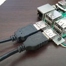
Normally you would use a FDDI cable or USBtoSerial converter cable to connect the ESP8266 module to your PC to program it. As I always look for the lowest cost solution (and didn't want to spend money for a FDDI cable) I searched and found that I could use my Arduino Uno to connect the ESP8266 to my PC.
Luckily the Adafruit HUZZAH ESP8266 has 2 important features that made it easier for me:
- 3.3V to 12V power input on Vbat and a 3.3V voltage inverter on board
- 5V to 3.3V level shifter for the serial RXD pin on board
So I had no problems to connect the ESP8266 directly to the Arduino Uno's serial port.
The attached file Programming board.fzz shows how to connect the ESP module to the Arduino Uno. The Uno itself is connected with the standard USB cable to the PC.
Of course the Uno should not use the serial port while the ESP8266 is connected to the RXD and TXD pins. The easiest way is to flash the Blink.ino example onto the Arduino Uno. This example is not initializing the serial port and the TXD and RXD lines can be used to program the ESP module.
After the Arduino Uno is running the Blink.ino sketch you can connect the ESP8266 to the Arduino board as shown in the attached Fritzing sketch Programming board.fzz.
Important note about the power supply:
As you can see in the schematic, I do not connect the 5V output of the Uno to the Vbat of the ESP8266. The ESP8266 is quite choosy with the power supply. In my first trials I supplied the ESP8266 from the 5V output of the Arduino board and got some weird errors while programming the ESP. It looks like the ESP (during the writing into the flash) needs more current than the Arduino can supply on the 5V line.
I chose to supply the Arduino from a 9V 2A supply and connect the ESP to the Vin pin on the Arduino. The Vin pin gets the 9V directly from the power supply. After that I had no more problems.
In the Arduino IDE (see above screenshot) in the Tools menu you have to select the correct board (in my case the Adafruit HUZZAH ESP8266) and the com port that the Arduino Uno is connected to. Then you can flash programs into the ESP module. Before flashing you have to set the ESP into programming mode. The Adafruit ESP8266 modules has 2 buttons to achieve this, the RESET and the GPIO0 button. The sequence to put the ESP into programming mode is:
- Press and hold RESET button
- Press and hold GPIO0 button
- Release RESET button
- Release GPIO0 button
After that the red LED on the Adafruit board will be on (but dimmed) and the board is ready to be programmed.
Additional note:
I needed to connect GPIO0 of the ESP8266 module to an unused GPIO of the Arduino board. If I leave the GPIO0 open, the programming was not working. Not sure about the reason.
WARNING:
I use specific features of the Adafruit HUZZAH ESP8266 module in this instructable. If you plan to build this system with an ESP8266 module from another supplier check carefully that it is compatible with the power supply I use and with the voltage level of the RXD pin. The Adafruit HUZZAH ESP8266 module accepts 3.3V to 12V power supply and has a level shifter on the RXD pin. If your ESP8266 module doesn't have these features you will definitely destroy your module!
All software sources and all schematics are available in my Github repository
Attachments
Step 4: The ESP8266 IR Remote Control Board


Now that the environment is up and you have recorded the IR commands it is time to build up the hardware for the IR remote.
The schematic is very simple. It is the ESP8266 module, a resistor, a transistor and 2 IR led. The GPIOs of the ESP can supply only a small current, that's why we use a transistor to switch the 2 IR leds on and off. I use 2 IR leds to get a better range, but it could work as well with only 1 led.
As you can see in the schematic, I did not add resistors in line with the IR leds. This is possible, because the IR leds are not ON for a long time, but are only pulsing with a frequency of 38kHz. If the transistor would connect them permanent to GND they would be destroyed.
As the 3.3V output of the ESP8266 has a limited supply current, I used the 5V instead to power the IR leds. The Adafruit HUZZAH ESP8266 has a voltage supply range of 3.3V to 12V. So it is easy to just use a USB charger adapter to power the whole module. But the USB charger adapter should supply at least 1A on the 5V to make sure the ESP module gets enough power.
It is important to use a good quality USB charger. Most cheap USB charger don't provide a clean 5V output. For just charging a cell phone or tablet it is not necessary to have a clean 5V level without noise. But as we are supplying an electronic board that seems to be choosy with its power supply, we need to make sure we have a good 5V supply. I didn't add it in the schematics, but on the pictures you can see that I added a 100uF electrolyt capacitor and a 10nF ceramic capacitor on the 5V supply to smoothen the 5V input and reduce noise.
As I am a cheapskate I was looking as well for a cheap case for the IR remote board. I found the solution with a small transparent container (that had yummy Herb Cream Cheese inside before). The transparency is good enough to let the IR light out to control the aircon. It is small enough to be placed anywhere (or even screwed to the wall). And as the electronics is inside the house I don't need any water proof housing.
All software sources and all schematics are available in my Github repository
Step 5: The Software for the ESP8266 Module - Part 1 "general Info"


The software for the ESP8266 module is divided into 2 slightly different versions that is applied to different ESP modules. It is possible to build up a small network of ESP8266 IR remote modules to control several aircons. But only one of them will be the "master" (or "one ring to control them all" according to "lord of the rings"). The other modules act as "slave" modules.
Version 1, the "master", is the software that is not only sending IR commands to an aircon, it is as well communicating with the solar panel monitor to get the actual power consumption of the house. The "master" is deciding when to switch on or off the aircon.
Version 2, the "slave", is the software that is sending IR commands to an aircon and it is receiving as well commands from the "master".
In the next steps I will explain the common software parts of both versions.
Step 6: The Software for the ESP8266 Module - Part 2 "common Commands"

Depending on the aircon, there will be different commands that can be sent to control the function. I tried to define a standardized set of commands that can be extended if other aircons with different commands are added.
For now the command set supports my FujiDenzo aircon and my Carrier model.
/** Definition of available commands *
#define CMD_ON_OFF		00

#define CMD_MODE_AUTO		10
#define CMD_MODE_COOL		11
#define CMD_MODE_DRY		12
#define CMD_MODE_FAN		13

#define CMD_FAN_HIGH		20
#define CMD_FAN_MED		21
#define CMD_FAN_LOW		22
#define CMD_FAN_SPEED		23

#define CMD_TEMP_PLUS		30
#define CMD_TEMP_MINUS		31

#define CMD_OTHER_TIMER 	40
#define CMD_OTHER_SWEEP 	41
#define CMD_OTHER_TURBO 	42
#define CMD_OTHER_ION		43

#define CMD_RESET		70

#define CMD_REMOTE_0		80
#define CMD_REMOTE_1		81
#define CMD_REMOTE_2		82

#define CMD_AUTO_ON		98
#define CMD_AUTO_OFF		99
Some commands are common to all types of aircons (like CMD_ON_OFF), others are specific for a certain type. For example the fan control commands. In the list are 4 commands to control the fan:
#define CMD_FAN_HIGH		20
#define CMD_FAN_MED		21
#define CMD_FAN_LOW		22
#define CMD_FAN_SPEED		23
On the FujiDenzo aircon I have 3 buttons to select a fan speed (low, medium or high, commands 20 to 22), but on the Carrier aircon I have only 1 button to toggle through the 3 possible fan speeds (speed, command 23).
Explanation of the commands:
Commands 00 to 49 are for control of the aircon. They are grouped by function (on/off, fan control, temperature control, other functions) I think you can guess from the command names what they are doing.

Commands 50 to 99 are for additional control of the ESP8266 module<br><br>CMD_RESET will force the ESP module to reset and start-up in default mode.

CMD_REMOTE_0 to CMD_REMOTE_3 are to control slave ESP8266 modules.
	CMD_REMOTE_0 switch off the aircon controlled by the slave ESP module
	CMD_REMOTE_1 switch the slave aircon on in fan only mode
	CMD_REMOTE_2 switch the slave aircon into cooling (or auto) mode

CMD_AUTO_ON and CMD_AUTO_OFF are used to enable or disable the power consumption controlled functionality.
Step 7: The Software for the ESP8266 Module - Part 3 "the Communication Interfaces"


Commands are received in string format over the serial or WiFi interface. The response to a command is send back as a JSON object.
The serial interface
The commands are formatted as 2 digit decimal numbers ("00" to "99") and must be terminated by a new line (\n). Commands send over the serial interface (e.g. from a terminal program) are received by checking the serial input buffer with
while (Serial.available()) {A command must be terminated with a new line code (\n). After a command line is received complete it is parsed by the parseCmd() subroutine. The commands are formatted as 2 digit decimal numbers ("00" to "99")
The WiFi interface
The commands are formatted as
IPADDR/?c=xx
Where IPADDR is the ip address of the ESP module and xx is the command (00 to 99).
It as well possible to request the status information from the module with
IPADDR/?s
And it is possible to start an initialization routine with
IPADDR/?r
The initialization routine tries to set the aircon into a default status (fan mode, low fan speed, temperature set to 25 degrees).
Commands over WiFi are received by a httpClient
// Handle new client request on HTTP server if available<br>	WiFiClient client = server.available();
	if (client) {
Then the command is parsed by the parseCmd() subroutine.
Step 8: The Software for the ESP8266 Module - Part 3 "the Command Parser"

The parser simply checks if a valid command was received over the serial or WiFi interface.
The parser checks as well if the command is an internal command (70 to 99) or a command that should be send to the aircon. Most aircon control commands are only accepted if the aircon is running. If the aircon is off, an error message is returned.
The result is saved as an JSON object that will be sent back to the requesting serial terminal or WiFi client. The JSON object can have the following entries:
result => fail, timeout, success depending on the result of the command<br>device => id of the aircon
cmd => the received command
power => the status of the aircon (on=1 or off=0)
mode => the mode of the aircon (fan=0, dry=1, cool=2, auto=3)
speed => the fan speed of the aircon (low=0, medium=1, high=2)
temp => cooling temperature of the aircon (value in degree Celsius)
cons => the energy consumption value (internal calculated from the last 10 readings)
status => the auto mode status (aircon off, in fan mode or in cool mode)
auto => whether the consumption controlled automation is enabled or disabled

Example response for the power on command:
{"result":"success","device":"fd1","cmd":0}

Example response for a status request:
{"result":"success","device":"fd1","power":0,"mode":0,"speed":0,"temp":25,"cons":465.09,"status":0,"auto":1}
Step 9: The Software for the ESP8266 Module - Part 3 "communication to the Aircon"

Sending IR commands to the aircon is done with the help of the IRremoteESP8266 library published as open source. The library supports already a wide range of protocols for different appliances, but offers as well to send "raw" IR commands. Unfortunately none of the implemented protocols worked with my aircons (even during recording the protocol was recognized as "NEC" for the FujiDenzo aircon). So I had to use the sendRaw() function.
The IR codes
To save memory space I saved the recorded commands as Byte arrays that contain only the marks (0 or 1) of the code, not the header or spaces. Example:
byte H_FAN[4] = {B00001000,B11100111,B01101000,B10010111};
byte M_FAN[4] = {B00001000,B11100111,B01110000,B10001111};
byte L_FAN[4] = {B00001000,B11100111,B01010000,B10101111};
The complete raw command is saved as:
unsigned int sendBuffer[67] = {9000,4500,450,0,450,0,450,0,450,0,450,0,450,0,450,0,450,0,450,0,450,0,450,0,450,0,450,0,450,0,450,0,450,0,450,0,450,0,450,0,450,0,450,0,450,0,450,0,450,0,450,0,450,0,450,0,450,0,450,0,450,0,450,0,450,0,450};9000 and 4500 are the header, all 450 values are the spaces and the zeros are filled with the values from the command Byte array with the sub routines buildBuffer() and getValue().
Sending the IR command
The function sendCmd() parses the requested command and builds up the correct sendBuffer by calling buildBuffer with a reference to the commands Byte array. Then the command is sent to the aircon with the sub routine sendCode(). As I said earlier, none of the available protocols of the IRremote8266 library did work with my aircons, so I needed to use the IRsend::sendRaw() function.
Step 10: The Software for the ESP8266 Module - Part 3 "setup() and Loop()"

setup()
The setup() function is called once after the ESP8266 bootet. Here I define the function of the GPIO pins, connect to the local WiFi, initialize the serial connection and start the HTTP server to receive.
Only on the "master" module I start as well a timer that triggers every 60 seconds an update of the power consumption (more about this in the next step).
WiFi connection
To make it easier to identify different ESP8266 modules I decided to use static IP addresses instead of using the DHCP function of my WiFi router.
Range 192.xxx.xxx.000 to 192.xxx.xxx.119 => DHCP assigned IP addresses for my PC's and laptops
Range 192.xxx.xxx.120 to 192.xxx.xxx.129 => IP address range used by my phones and tablets (static IP address)
Range 192.xxx.xxx.140 to 192.xxx.xxx.150 => Home automation, this range is used by my Arduino and ESP8266 modules
    192.xxx.xxx.140 => Solar panel monitoring system
    192.xxx.xxx.141 => Security system
    192.xxx.xxx.142 to 192.xxx.xxx.148 => ESP8266 modules for appliances control
To connect with a static IP address, some additional parameters have to be used with WiFi.config():
WiFi.mode(WIFI_STA);<br>	WiFi.config(ipAddr, ipGateWay, ipSubNet);
	WiFi.begin(ssid, password);
	Serial.print("Waiting for WiFi connection ");
	while (WiFi.status() != WL_CONNECTED) {
		delay(500);
		Serial.print(".");
	}
ipAddr => the ipAddr assigned to this module
ipGateWay => the default gateway (usually the IP address of the router)
ipSubNet => the IP mask for all local IP addresses, in my case 255.255.255.0
WARNING - Arduino OTA function
The Arduino ESP8266 libraries offer as well an OTA function (software update over WiFi). This would be a nice function to update my ESP8266 modules without connecting them by serial connection to the PC.
Unfortunately my experience with this function is very bad. In 70% of my trials the transfer of the new software over WiFi was corrupted and after Reset the module was hanging and not responding. Only a reflash over serial connection brought them back to work.
I have the OTA function in my code, but I do not use it anymore. Hopefully with a later update of the ESP8266 libraries the OTA function will be more reliable.
loop()
The loop() function is the main program loop (as the name says). Here I check if a new client has connected over WiFi, if a command has been received over serial connection or (only for the "master" module) if an update of the power consumption has been triggered (more about this in the next step.
Step 11: The Software for the ESP8266 Module - Part 4 "master Functions"

As said before, there are 2 versions of the software.
The "master" version reads the power consumption from the solar panel monitoring system and decides when to switch on or off an aircon.
The "slave" version receives commands from the "master" version.
The additional master functions:
1) Update power consumption value
To update the power consumption a timer is used to trigger every 60 seconds a connection to the solar panel monitor in setup():
getPowerTimer.attach(60, triggerGetPower);
This calls every 60 seconds the interrupt routine triggerGetPower(). As interrupt routines MUST be short and not delaying other functions, it is not possible to start the update directly from here. Instead the flag powerUpdateTriggered is set to true which that tells the loop() function that an update is necessary. As interrupt routines MUST be short and not delaying other functions, it is not possible to start the update directly from here. Instead
In loop()
if (powerUpdateTriggered) {checks this flag and calls the getPowerVal().
getPowerVal() connects via a TCP connection to the solar panel monitor and receives the latest power consumption value in a JSON object. The power value is stored in an array with a capacity of 10 values.
If 10 values are available then the checkPower() function is called to decide if it is necessary to switch on additional appliances to consume excessive power.
If more than 10 values are stored, the oldest value is discarded and the newest value is stored.
2) Check power consumption average
In checkPower() the average of the last 10 power values is created. During windy and cloudy days, the power production of the solar panels can jump quickly from a few Watts to several 100 Watts. Using the average of the last 10 values avoids switching on and off the aircon every minute (which is not good for the aircon).
Depending on the result and the current control loop status actions are taken:
if control loop status is 0 (aircon is off)
   if excessive power is greater than 100 Watt
      switch on aircon in fan mode
      switch control loop status to 1
if control loop status is 1 (aircon is in fan mode)
   if excessive power is greater than 400 Watt
      switch aircon to cool mode (to consume more power)
      switch control loop status to 2
   if consumed power is greater than 200 Watt (the consumption is higher than the production)
      switch off the aircon
      switch control loop status back to 0
if control loop status is 2 (aircon is in cool mode)
   if consumed power is greater than 400 Watt (the consumption is higher than the production)
      switch the aircon back to fan mode
      switch the control loop status back to 1
This control loop is using only one aircon to consume excessive power. In the source code you can see another control loop that uses 2 aircons to consume excessive power. I am still testing this loop and it is not fully functional yet.
Step 12: The Software for the ESP8266 Module - Part 4 "slave Functions"

The "slave" software is missing the timer for consumption updates and the control status loop. Instead it is controlled by the "master" with three commands to switch the aircon into fan mode, cooling mode or off. The commands are received by the same interfaces for serial and WiFi communication that are used in the "master" software version.
The three remote commands are processed in the main program loop():
if (irCmd == CMD_REMOTE_0) {<br>	if ((acMode & AC_ON) == AC_ON) { // AC is on
		irCmd = CMD_MODE_FAN;
		sendCmd();
		delay(1000);
		irCmd = CMD_ON_OFF;
		sendCmd();
	}
	irCmd = 9999;
}<br>if (irCmd == CMD_REMOTE_1) {
	if ((acMode & AC_ON) != AC_ON) {
		irCmd = CMD_ON_OFF;
		sendCmd();
		delay(1000);
	}
	irCmd = CMD_MODE_FAN;
	sendCmd();
	irCmd = 9999;
}

if (irCmd == CMD_REMOTE_2) {
	if ((acMode & AC_ON) != AC_ON) {
		irCmd = CMD_ON_OFF;
		sendCmd();
		delay(1000);
	}
	irCmd = CMD_MODE_AUTO;
	sendCmd();
	irCmd = 9999;
}
Step 13: The Software for the ESP8266 Module - Part 4 "different Aircon Communication"
Most aircon manufacturer are using different type of commands. For me I investigated the how the IR commands are transferred for two manufacturers, FujiDenzo and Carrier.
FujiDenzo aircon:
- Each command consists of 67 values of headers, marks and spaces.
- The same code is sent even if a button is pressed repeatedly.
- Each code is sent only once a button is pressed
Carrier:
- Each command consists of 51 values of headers, marks and spaces.
- Each command has three different sets of IR pulses.
- If a button is pressed repeatedly, the code loops through the three different sets of IR pulses.
- Each code is sent three times once a button is pressed.
These differences must be reflected in the different versions of the software.
The different IR pulses are stored in the files IR-FujDenzo_0_Codes.ino and IR-Carrier_0_Codes.ino
The software for the Carrier aircon has a counter that is used to know which of the three sets of IR pulses needs to be used and a variable to check whether a command is repeated.
/** Last processed command (from lan or serial connection) */
int lastCmd = 99;
/** Counter to check if command is repeated */
byte cmdCnt = -1;
The routine chkCmdCnt() checks if a command is repeated and change the counter cndCnt if necessary
void chkCmdCnt() {<br>	if (irCmd == lastCmd) {
		cmdCnt ++;
		if (cmdCnt == 3) {
			cmdCnt = 0;
		}
	} else {
		cmdCnt = 0;
		lastCmd = irCmd;
	}
}
The sendCmd() function is different for FujiDenzo and Carrier.
FujiDenzo Carriercase CMD_ON_OFF: // On-Off
if ((acMode & AC_ON) == AC_ON) { // AC is on
// set power bit to 0
acMode = acMode & AC_CLR;
acMode = acMode | AC_OFF;
isValidCmd = true;
} else {
// set power bit to 0
acMode = acMode & AC_CLR;
acMode = acMode | AC_ON;
isValidCmd = true;
}
buildBuffer(&sendBuffer[0], &POWER[0]);
break;
case CMD_ON_OFF: // On-Off
  if ((acMode & AC_ON) == AC_ON) { // AC is on
    // set power bit to 0
    acMode = acMode & AC_CLR;
    acMode = acMode | AC_OFF;
    isValidCmd = true;
  } else {
    // set power bit to 0
    acMode = acMode & AC_CLR;
    acMode = acMode | AC_ON;
    isValidCmd = true;
  }

  chkCmdCnt();
  switch (cmdCnt) {
    case 0:
      buildBuffer(
          &sendBuffer[0],
          &POWER_0[0]);
      break;
    case 1:
      buildBuffer(
          &sendBuffer[0],
          &POWER_1[0]);
      break;
    case 2:
      buildBuffer(
          &sendBuffer[0],
          &POWER_2[0]);
      break;
  }
 break;
As you can see in the Carrier software the function chkCmdCnt() is called before the sendBuffer is build while in the Denzo software the same IR pulses are used always to build the sendBuffer.
Step 14: Summary


So with this small ESP8266 module, a transistor, a resistor, 2 IR leds and a little bit of software I implemented the next step of my home automation and energy saving project.
It is not working perfect yet, and I am testing and updating the software continuously.
All software source code, schematics, breadboard sketches and PCB layouts can be downloaded from my Github repository.
And there is always one problem. If the aircon is switched on or off, or the aircon mode is changed with the original IR remote control, the ESP8266 doesn't know about it and its internal status is no longer valid. One way to avoid this is to just bury the original aircon remotes somewhere, so that they cannot be used at all. But sometimes you just need your aircon to cool, even the solar panels are not harvesting enough energy.
To go around this problem I decided to take the project to the next level and create an Android application to control the aircons manually by sending commands to the ESP8266 modules.
More about that in the next step.
Step 15: Android Apk to Communicate With ESP8266 Aircon Remote Modules


I created this Android apk to have control my aircons with the help of the ESP8266 aircon remote modules. This application can run on several phones and tablets in parallel without any problems, as the last status of the aircon (or better of the ESP8266 module that is controlling it) is known by all of devices.
The application currently supports 2 aircon types, the FujiDenzo and the Carrier that I own. The screen layout changes to reflect the different available functions for each of these aircons.
FujiDenzoCarrierThe different aircons are selected by the buttons in the top bar, showing icons for the office (FujiDenzo aircon) and living room (Carrier aircon). If more than 2 ESP8266 aircon controllers are found, they are listed in the menu (most right icon in the top bar).
The menu gives access to additional functions
- Refresh reads the last status of the connected aircon controllers
- Search searches the local network for aircon controllers
- Enable Debug enables the output of debug informations
- Locations allows the user to select names and icons for the different aircon controllers
When pressing locations, first a dialog is shown to select the device to be changed:
After selecting a device, a new dialog is shown where the display name and the icon can be changed:
At the moment 8 different icons are implemented for
- Shower/bathroom
- Bedroom
- Dining room
- Entertainment room
- Kids room
- Kitchen
- Living room
- Office
I will not go into details of the Android code. You can find the source code in my Github repository to check it. If you have any questions, please leave me a comment below.

Participated in the
Arduino All The Things! Contest


