

Introduction: ESP8266 As Arduino


ESP8266 as Arduino
So this Lazy Old Geek (L.O.G.) heard about this ESP8266 IC. Basically, it’s a microcontroller that does WiFi. There are many Instructables with this chip and many with an Arduino. But most of these are using the ESP8266 as a sensor/WiFi connected to a standard Arduino.
Well, what I wanted to do was use the ESP8266 as an Arduino without having to use a standard Arduino.
The ESP8266 is a microcontroller similar to the AtMega328 used in the standard Arduino, e.g., Arduino UNO.
Now there is already a lot of information on doing this but I found it confusing, hard to figure out, sometimes misleading so I hope to simplify and clarify the process.
Special thanks to Lady Ada, Adafruit and the Adafruit HUZZAH ESP8266 breakout module. As usual she provides thorough, useful information.
Also, much of my information comes from this website:
https://github.com/esp8266/arduino
There are many versions of ESP8266s. Some of the cheaper ones are ESP-01, ESP-03. I think right now they go up to ESP-12. Plus there are other variations.
ESP-01 $2.88 ebay
ESP-03 $2.25 ebay
Cheaper on aliexpress.com
Step 1: Hardware Problems


Most communications with the ESP8266 is serial. Most computers use USB to serial converters, like FTDI chips.
PROBLEM: The ESP8266 IC requires 3.3Vdc instead of the more common 5Vdc. Also, it may need up to 250mA of current.
SOLUTION1: So some ESP8266 modules have built in 3.3Vdc regulators and are compatible with 5Vdc USB to serial devices.
Adafruit HUZZAH ESP8266 Breakout(https://www.adafruit.com/products/2471)(see picture)
SOLUTION2: So many FTDI converters have the option of converting logic to 3.3Vdc. And most have a 3.3Vdc supply. The problem is that most of the power supplies are in the FT232 IC and are only capable of supplying about 50mA of current. (see picture) This is also true of the PL2303 serial converters that I use a lot of.
So a separate 3.3Vdc power source is needed.
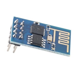
PROBLEM: The ESP-01 module has 2x4 header that is not compatible with breadboards.(see first picture)
SOLUTION: I took some long lead female headers and bent them with a little S-curve so that they will fit in a breadboard. (see pictures)
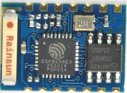
PROBLEM: The ESP-03 module has 2mm spacing on connectors which are not compatible with 0.1” breadboards.
SOLUTION: I have some 2mm headers so I soldered some male pins to the ESP-03. (see picture), then I took some 2mm female headers and wired them to some 0.1” headers. In this case I soldered them to a 2x4 headers so that I could plug them into the connector for the ESP-01.
Well, this works pretty good for breadboarding. (see picture) but I wanted something more permanent so I may make it into a PCB.
Step 2: ESP8266 As Arduino

Okay, there are many articles on how to do this. Most are very confusing. One of the better ones is:
https://learn.adafruit.com/adafruit-huzzah-esp8266-breakout/using-arduino-ide
The one I used the most is:
https://github.com/esp8266/arduino
ESP8266 Requirements
Hardware:
3.3Vdc supply 250mA or greater. I used an AMS1117 3.3 regulator. This is powered by USB 5V. (The USB requirement is that the 5Vdc has a minimum 500mA of current.)
USB to Serial 3.3Vdc. I use a PL2303 device.
******************************************************************************
WARNING: Some newer PL2303 modules have 5Vdc on TX. This could damage the ESP8266 modules.
******************************************************************************
Software:
Arduino Environment v 1.6.4 or greater
ESP8266 Setup
Software:
These are instructions from https://github.com/esp8266/arduino
Installing with Boards Manager
Starting with 1.6.4, Arduino allows installation of third-party platform packages using Boards Manager. We have packages available for Windows, Mac OS, and Linux (32 and 64 bit).
Install Arduino 1.6.4 (or greater) from the Arduino website. Start Arduino and open Preferences window. Enter http://arduino.esp8266.com/package_esp8266com_ind... into Additional Board Manager URLs field. You can add multiple URLs, separating them with commas. Open Boards Manager from Tools > Board menu and install esp8266 platform (and don't forget to select your ESP8266 board from Tools > Board menu after installation).
Connections:
ESP-01
UTXD RXD of USB-Serial
CH_PD 3.3V
Reset Pushbutton to Gnd
URXD TXD of USB-Serial
GPIO0 Pushbutton to Gnd
GPIO2
GND GND
TIPS: Make sure TX from serial goes to ESP-01 URXD and RX goes to UTXD
On my breadboard setup, instead of pushbuttons, I used two pin jumpers.
Procedure:
Connect USB-serial to PC and ESP-01, connect power if separate
Start Arduino 1.6.4
Select ‘Tools’ ‘Port’ whatever # your USB-serial is on
Select ‘Tools’ ‘Board’ ‘Generic ESP8266 Module’
Select ‘Tools’ ‘CPU Frequency’ ‘80MHz’ Not sure why
Select ‘Tools’ ‘Flash Size’ ‘512K (64K SPIFFS)
Select ‘Tools’ ‘Upload Speed’ ‘115200’ Some ESPs may be 9600
Put ESP8266 into Flash mode:
Ground GPIO0
Briefly ground Reset
Release GPIO0
(If you have an LED on GPIO0, it should be about ½ intensity)
Load a sketch. (You can use Blink if you change it from D13 to D2)
If it works, In the Arduino environment bottom window, you will see a string of red dots as it is programming.
TIPS: While the sketch is programming, the blue LED on the ESP-01 will flash. If you have an LED on GPIO0, it will turn off when programming is complete.
So if you’re lucky and followed my instructions you should have successfully programmed the ESP-01 with Arduino
For the ESP-03, you would expect the same procedure to work but not quite.
First you have to connect a 10K resistor from GPIO15 to ground.
Second it doesn’t have an easily accessed Reset pin.
Well, I did some research and apparently the CH_PD pin when pulled to GND will work as a Reset.
Connections:
ESP-03
UTXD RXD of USB-Serial
CH_PD 1K resistor to 3.3V
CH_PD Pushbutton to Gnd
URXD TXD of USB-Serial
GPIO0 Pushbutton to Gnd
GPIO2
GND GND
GPIO15 10K to ground
Put ESP8266 into Flash mode:
Ground GPIO0
Briefly ground CH_PD (Reset)
Release GPIO0
(If you have an LED on GPIO0, it should be about ½ intensity)
So this also works for the ESP-01.
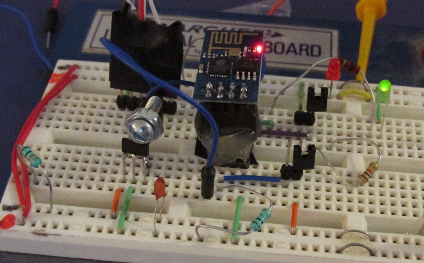
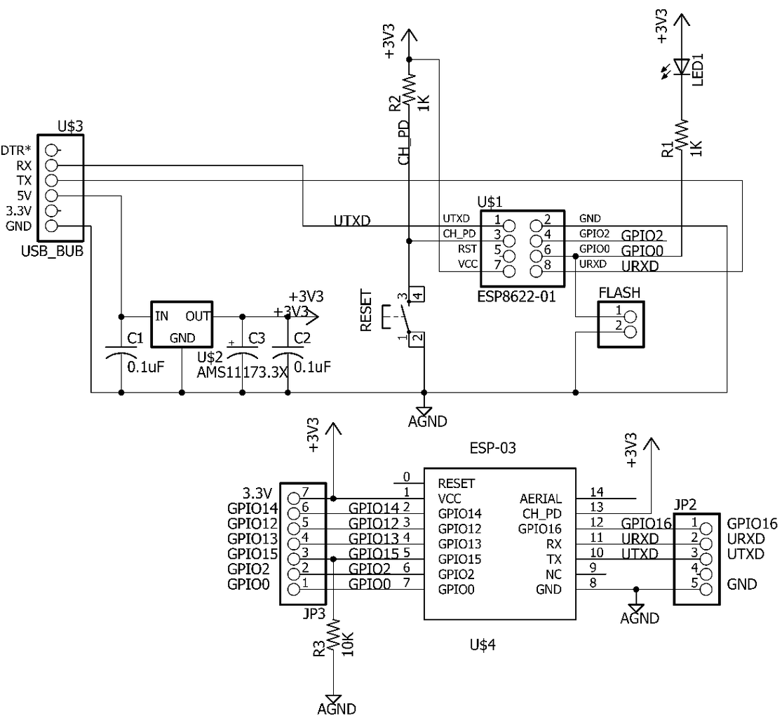
Here is a schematic of my breadboard setup.
Step 3: Firmware
What I discovered was that loading sketches overwrites the original software which is used by many of the basic Instructables and probably with a lot used when the ESP8266 is connected to a standard Arduino.
So I needed a way to reflash it back to ‘original’ software.
The one I use is ESP8266_flasher.exe
https://drive.google.com/file/d/0B3dUKfqzZnlwVGc1YnFyUjgxelE/view?pli=1
This is on Google Drive. Up at the top there is a little icon down arrow that will say Download. Load it to your PC.
Now there is a version of firmware there but it’s not the latest.
Official version?
Again, this is Google Drive.
What I did is click on 0.952 support Smar
Then click on v0.9.5.2 AT Firmw
Then click on Download and save it to your PC remembering where it is.
Procedure:
Run ESP8266_Flasher
Click on ‘Bin’ , select bin file
Select correct COM port
Now setup ESP8266 into flash mode as above.
Click on ‘Download’
Program should start Writing. This takes a while
Says Leaving… Failed to leave Flash mode
Ignore message, should be finished.
Test
Easy way to Test is to use Arduino, select port, open serial monitor
Set it to 115200 baud rate and Both NL & CR
On command line enter AT+RST
NOTE: I just noticed it says SPI Speed: 40MHz,( though crystal is 26MHz)
On command line enter AT+GMR
SDK version: 0.9.5
Step 4: Conclusions
So this seems to work pretty reliably.
You don’t have to load a bootloader onto the ESP8266.
It does seem to take a little longer to program/flash.
It’s a little harder to set it up for flashing. But I’m looking into automating some of that with an FT232 module. (My old USB-BUB doesn’t work anymore.)
I need to explore some of the WiFi capabilities of the ESP8266.

![Tim's Mechanical Spider Leg [LU9685-20CU]](https://content.instructables.com/FFB/5R4I/LVKZ6G6R/FFB5R4ILVKZ6G6R.png?auto=webp&crop=1.2%3A1&frame=1&width=306)


