

Introduction: Easy Project - Control an LED Light With Python Using a Raspberry Pi


This will be the easiest Raspberry Pi GPIO LED project ever. If you follow this guide it should take less than 20 minutes to setup and have running. The goal of this project is to get a single LED light blinking based on a Python program running on a Raspberry Pi. In order to do this you will need to use the GPIO pins (the gold colored ones near the SD card and S-video) on the Raspberry Pi. This article will go over materials needed, how to setup the hardware and example software code. This project is meant to be simple for Noobs.
This Post is originally from Tech4Noobs.com
Step 1: Materials Needed
Raspberry Pi and all of the basics - Everything needed to get the Raspberry Pi up and running can be found in the Raspberry Pi is an Amazing Small Learning Computer and Starting the Raspberry Pi for the First Time is Easy Articles previously published on this website. These articles will show you were to buy all of the Raspberry Pi basics and how to get it up and running with Raspbian.
Additional Electronics Needed - Below is a list of items you will need for this project. If you do not have these items lying around the house there are also product links on kits we bought and liked on Tech4Noobs.com.
Jumper wires or leads (male to female) - These are cheap small wires to connect the GPIO pins to the breadboard. If you are just starting out we suggest getting male to female leads for easy connection to the Pi. This is what we bought for $9. Foxnovo 3pcs 20cm Multicolored 40-pin Male to Female /Male to Male /Female to Female Breadboard Jumper Wires Ribbon Cables
Additional Resistors - These are cheap and you can never have enough if you plan to do some projects. E-Projects - 400 Piece, 16 Value Resistor Kit (10 Ohm - 1M Ohm)
A Starter Kit - Might be the easiest way to go instead of buying a bunch of things individually.
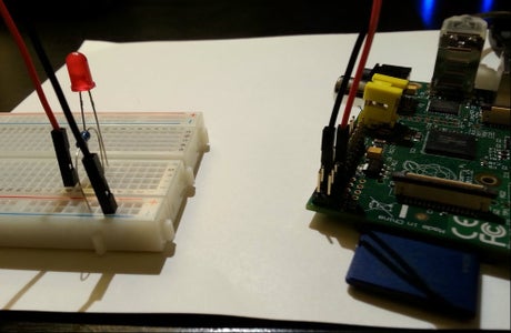
Step 2: Hardware Configuration

Make sure the Raspberry Pi is unplugged!
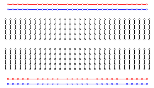
Quick breadboard explanation - breadboards are pretty simple tools. They simply allow for connecting wires together without having to solder anything. In a breadboard there are horizontal relays of 5 slots each and vertical relays of 25 slots. Each row of 5 and 25 is connected together but not to each other. The picture to the right gives a visual on how things are electrically connected.
Jumper Wires - Take two female to male jumper wires (I suggest using red and black if you have them for positive and negative) and connect the red one to GPIO pin 7 and the black one to GPIO pin 6 (see the diagram above for a visual on how the pins are numbered). After this connect the red wire to a horizontal relay section on the breadboard. For this example we will connect to slot j9 on the breadboard. Connect the black wire to any of the vertical negative (blue) relay channels.
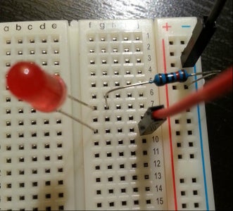
LED Light - Pick any color you like. You will notice that the LED has one connection that is longer than the other. The longer one is the positive and the short end is the negative. Plug the positive (longer) end into the same channel on the breadboard as your positive (red) wire. In this example we will use slot f9. Plug the negative (shorter) in any horizontal channel that is not in the same as the positive connection. In this example we will use f7.
Resistor - Use between a 220 Ohm and a 270 Ohm for this. If you bought the resistor kit above everything will be labeled. If you did not use this online calculator. Plug one end of the resistor into the same horizontal channel that the negative end of the LED is plugged into. For this example we are using slot g7. Plug the other end into the negative vertical relay channel (blue) so it is connected with the negative (black) jumper wire.
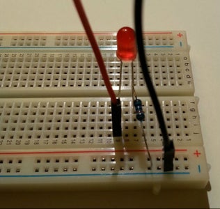
Final Hardware Configuration - When everything is said and done the breadboard should look something like the above picture. I know it is hard to see.
Step 3: Software Code
Opening IDLE - IMPORTANT: The first step in the software is to go to the Pi's terminal. I know this is scary for us Noobs but we will only be in there a second. Open the terminal on the Pi and type the below command. This will get you into super user (sudo) mode. If you do not do this the program will not run.
sudo idle
Creating a New File - Once in idle navigate to file (top left corner just like Windows) then navigate to new window. This will open a new file that is outside the Python shell.
Writing the Program Code - Below is our example program we will use. Below that are some explanations of the code.
import RPi.GPIO as GPIO
import time
GPIO.setmode(GPIO.BOARD)
GPIO.setup(7,GPIO.OUT)
for x in range(0,5):
GPIO.output(7,True)
time.sleep(2)
GPIO.output(7,False)
time.sleep(2)
GPIO.cleanup()
Explanation
import RPi.GPIO as GPIO - This imports the GPIO library for Python
import time - This imports the time library for Python
GPIO.setmode(GPIO.BOARD) - This defines what numbering scheme the pins use. This is the simplest because it follows the chart above.
GPIO.setup(7,GPIO.OUT) - This tells Python to use pin 7 where the positive wire is plugged in
for x in range(0,5): - This sets the loop for how many times you want the LED to turn on and off. Right now it will turn on and off 5 times.
GPIO.output(7,True) - This tells Python to turn on pin 7
time.sleep(2) - This tells Python to leave pin 7 on for 2 seconds
GPIO.output(7,False) - This tells Python to turn off pin 7
time.sleep(2) - This tells Python to stay off for 2 seconds
GPIO.cleanup() - This just cleans everything up after it is complete
Step 4: Final Result - Silly Video
Watch the Final Product on YouTube
The inspiration for this project came from Learning Computers. This is the the YouTube video
Building On This Project
Here are a few ideas to add to this project.
Add more LED lights - The only thing better than one blinking LED on a breadboard is many blinking LED lights
Integrate a button into the circuit - Make the Python program run by pushing a button on the breadboard as opposed to hitting your keyboard.


