

Introduction: Educational Colorimeter Kit


This instructable is a step-by-step assembly guide for the educational colorimeter kit we launched in April 2012 on Kickstarter. Assembly takes from 20-40 minutes. Once assembled the colorimeter can be used in a wide variety of science experiments to measure the absorbance and concentration of a colored solution.
The colorimeter kit is an open source hardware project: KiCad files for the electronics, enclosure designs and software are hosted and updated here: https://bitbucket.org/iorodeo/colorimeter/. For those interested in making their own boards and laser cut parts we have included the Gerber files for the 3 PCBs with BOMs, as well as the files for the laser cut parts. A list of all additional materials (hardware etc) can also be found in the online User Manual.
For more information on the educational colorimeter kit, visit the project website at www.iorodeo.com/colorimeter and the Kickstarter project at http://www.kickstarter.com/projects/iorodeo-colorimeter/educational-colorimeter-kit
There is now a video of the assembly at the end of this instructable in Step 8.
Step 1: Kit Contents:


Kit contents:
Each Kickstarter colorimeter kit ships in a 6" x 4" x 3" clear container and contains the following items:
- Colorimeter LED board
- Colorimeter sensor board
- Colorimeter shield for the Arduino
- 11 laser cut acrylic parts for the light-tight enclosure
- Hardware for the enclosure (screws, nuts, washers and standoffs)
- 4 x pre-crimped 3" colored wires and housing
- Assembled ribbon cable for connecting the Arduino and colorimeter
- Set of 6 cuvettes
- Mini Philips screwdriver
Step 2: Identify the Laser Cut Parts

Download the attached PDF
Print out and lay on a flat surface
Take all of the black laser cut acrylic parts and match them with the outlines on the printout. This will help to identify the parts as you go through the next three steps in this instructable.
Attachments

Step 3: Assemble Colorimeter Base


Kit Parts: Base plate, 2 x cuvette holders, 4 x 1¾” long standoffs, 2 x 1¼” long standoffs, 8 x 3/8" screws, 4 x rubber feet.
Step A. Place one of the cuvette holders on the base plate with the U-shape facing center. Secure in place with a screw and the two 1¼” standoffs.
Step B. Mount the second cuvette holder onto the standoffs with two screws.
Step C. Place one of the 1¾” standoffs in each corner of the base and secure in place with a screw.
Step D. Place one of the rubber feet in each corner of the base plate.
Step 4: Mount and Connect the Colorimeter Sensor and LED Boards


Kit parts: Sensor mount, LED mount, Divider Wall, Sensor board, LED board, 4 x colored wires and 2 x connector housing.
Step A. Mount the sensor board onto the black acrylic sensor mount as shown in the image so that the shrouded header pokes through the hole in the acrylic. Secure in place with four 3/8" screws and four of the nuts.
Step B. Mount the LED board onto the LED mount. Make sure that the board is mountedcorrectly - it is easy to accidentally mount this board upside down. Check with the image to make sure you have the correct orientation. Secure in place with four 3/8" screws and the four remaining nuts.
Step C. Take one of the black plastic housing connectors and the four pre-crimped wires. Locate the triangle marker on the housing. This denotes Pin 1, which is the black ground wire. Push the black wire through the connector until it clicks into place. Next insert the red wire, followed by the green wire, and finally the blue wire. Make sure all wires are held firmly in place and do not come out of the housing when you gently pull on the end.
Step D. Thread the free ends of the four colored wires through the hole in the divider wall. Make sure the orientation of the part matches the images shown here.
Step E. Take the second connector housing part and repeat inseting the wires as before - start by locating the triangular marker and insert the black wire first into this hole followed by red, green and finally blue.
Step 5: Assemble the Rest of the Enclosure


Kit parts: All remaining acrylic parts, 4 x washers, 4 x 1/2" long screws.
Step A. Place the assembled electronics part from the previous step onto the base plate from Step 1.
Step B. Take the two side walls and slot them onto the base plate so that all the parts click together.
Step C. Place the top plate on top. All the parts should now easily sit in place securely.
Step D. Lay the outer slider and inner slider onto the top plate.
Step E. Finally place the four washers in each corner and place the clear cover on top. Secure all the parts in place with the four 1/2" screws. Tighten all the parts in place with the screwdriver.
Step 6: Download Open Source Software


Arduino firmware - Download and save the Arduino firmware from www.iorodeo.com/software/colorimeter. Open the Arduino firmware in the Arduino IDE, compile and upload to your Arduino board.
Software - Download and save the colorimeter software executable (Windows or Linux) from the same website as above. Note, for the Linux version, you will need to make the file executable before it can be run.
Note that source files for all of the above software are available for download on the project Bitbucket site at http://bitbucket.org/iorodeo/colorimeter/src.
Step 7: Connect the Colorimeter to the Arduino

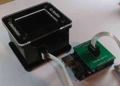
Step A. Place the Arduino shield onto your programmed Arduino board from Step 6.
Step B. Use the ribbon cable to connect the colorimeter to the shield.
Step C. Launch the colorimeter software program downloaded in the previous step. Select the serial port and click Connect.
Step D. To check everything is working correctly, slide open the colorimeter so that you can see the LED inside the device. In the program click on the calibration button. You should see the LED rapidly cycle through the red, green, blue LEDs.
Step 8: Start Measuring ....
- Fill a cuvette with approximately 1mL of water and place it into the cuvette holder. Slide the lid closed.
- Click on the "calibration" button in the program. All four channels should now display a transmission of 1.0 and an absorbance of 0.0.
- Fill a second cuvette with your sample, for example diluted blue food dye. Place this in the colorimeter and press the "measure" button. The absorbance measurements for the blue food dye will be displayed. If the solution is too concentrated you may need to dilute it further to obtain an absorbance measurement.

Participated in the
Arduino Challenge

Participated in the
Make It Real Challenge


