

Introduction: Enclosure for the Blinky Makey PCB


Enclosure for the Blinky Makey PCB
The Change Log can be found in the last step.
A little story...
At this year's Maker Faire Vienna I bought Blinky Makey for my kids and myself. It is a kit to learn to solder. (If you want to read more about the board, have a look at the STEP More about Blinky Makey.)
Back home we unpacked it and started to assemble everything. After half an hour Makey was ready for a test. So we put the battery in place, switched it on and the light show started.
The finished kit can be worn around the neck with a lanyard. For visits at a Maker Faire quite useful, but rather unsuitable at home.
So what to do with the finished kit after soldering?
- Storing it inside drawers => No!
- Laying it on the table => Maybe ..., but No!
- Position it upright on the table => Yes!
But how to achieve that?

After some brainstorming, I decided it would be best to put Makey in a kind of "Snap-Fit Enclosure" which looks like an additional skin or armor around the PCB.
No sooner said than done.
Let's go!
In this Instructables, I want to show you - How to build an Enclosure for the Blinky Makey PCB.
Step 1: Tools, Materials and Software That I Used
Tools, Materials and Software that I used
Tools:
- Caliper
- Office Scanner
- Dremel 3D Printer
Materials:
Software:
Step 2: More Informations About Blinky Makey


More Informations About Blinky Makey
German text provided by heise online, Make: Magazin
Blinky-Makey is a soldering kit which you can find on D/A/CH region (German speaking) Maker Faires like Vienna, Berlin and Hanover. It can also be ordered in the heise online shop.
It is made to learn to solder. The first soldering experience. Normally you will do this directly at a Maker Faire at the Make Magazine booth.
23 components must be soldered to the robot board, then his eyes and belly are blinking. On the top side are ten red LEDs, which are controlled by the circuit (bottom side). Thanks to two potentiometers, the flashing can be adjusted individually. One poti controls the rise time and the second the fall time of the flanks. There are five small measuring points (TP1 ... TP5) on the board, which can be used to measure the supply voltage and various signal forms in order to understand the behavior of the NE555. The necessary power is supplied by a replaceable CR2032 button cell battery.
Content of the kit (Version2)
- Makey board 70 x 72 x 1,5mm
- 26 components
- 1x PCB
- 2x Potentiometer
- 10x Red LED's
- 1x Capacitor
- 1x Battery holder
- 1x CR2032 button cell
- 4x Resistors
- 1x Diode
- 2x Transistors
- 1x Switch S1 (Turn the Makey On/Off)
- 1x IC socket
- 1x NE555 IC
Step 3: Design


Design
I used Fusion360 to create the enclosure. If you are new to this topic, I can recommend the 3D DESIGN CLASS.
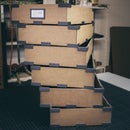
I placed the front and back of the unsoldered board on an office scanner to create a digital image of it.
The procedure with Adobe Photoshop

Step 1:
I opened the file from the scanner in Adobe Photoshop.
---

Step 2:
I cut and rotated the picture so that the foot of the robot is horizontal aligned.
---

Step 3:
I used the Magic Wand with a tolerance of 20 to eliminate the background around Makey.
---

Step 4:
I changed the background to black to get a better contrast. At a very high zoom rate, I used the Eraser and started with the fine-tuning to create nice edges.
---

Step 5:
After that, I duplicated the layer, opened the Layer Style and added a 1px Stroke around the PCB.
---

Step 6:
Last but not least I changed the Fill Opacity to 0 so that I only saw the frame. I saved this as MakeyOutline.png and the second layer as MakeyBack.png.
I repeated the steps above with the front scan of the PCB so that I have also a MakeyFront.png.
---
---
The procedure with Autodesk Fusion360
Step 1:
I attached the MakeyOutline as a Canvas to Fusion. At this moment I ignored the scaling, but I fixed it in a further step.
---

Step 2:
With the Spline tool, I traced the outline and created the main shape as a sketch.
TIPP: Use multiple splines to create the final shape. It is much easier to modify it afterward. Don't use a single spline for the whole object.
---

Step 3:
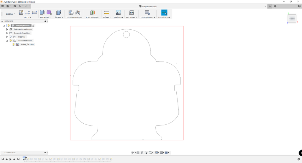
I extruded the sketch to 1.5mm which is exactly the thickness of the PCB.
---

Step 4:
I scaled it to its final shape. The reference point was the foot of Makey with a length of 44.8 mm. After that, I created two offsets. The first 0.5mm around the PCB to give it some space to "breathe" and the second with an offset of 2mm as the outer contour. This results in a 1.5mm thickness of the enclosure.
---
Step 5:
With the help of a caliper, I measured the thickness of the soldered PCB. 11.5mm. For that reason, I extruded the sketch to 12mm.
---

Step 6:
I attached the MakeyBack as a second Canvas to Fusion360.
---

Step 7:
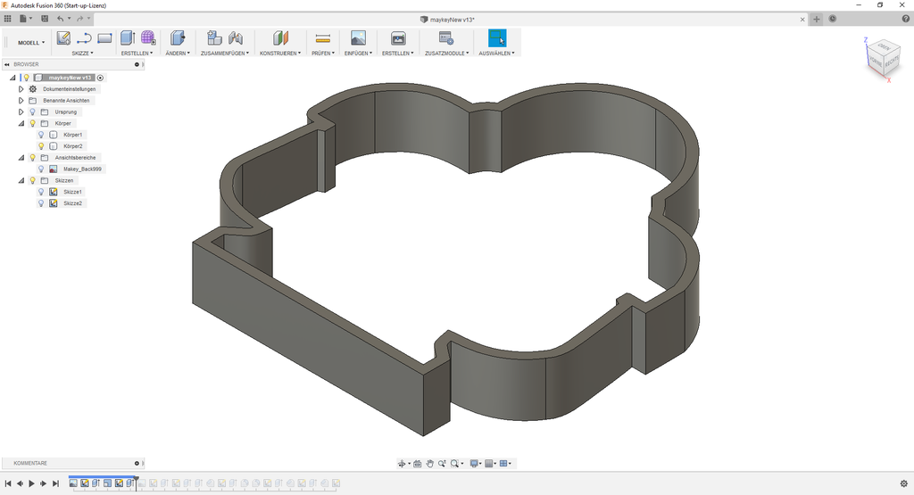
On the back of the shape, I created a 1mm thick bottom.
---

Step 8:
With the help of the MakeyBack Canvas, I sketched three recesses (two for the poti, one for the on/off switch) and four pillars to the enclosure bottom.
Diameter
- Recesses 11mm
- Pillars 6mm
---

Step 9:
I extruded the pillars to 10mm and deleted the three recesses. To stabilize the pillars, I added a 1.5mm Fillet to the bottom.
---

Step 10:
On the front of the enclosure, I created another sketch for the mechanism to hold the PCB in place.
---
Step 11:
I extruded this basic structure to 3mm.
---

Step 12:
For a nicer look, I used the Fillet tool to smooth out the edges.
---


Step 13:
In the last step, I created tabs on the inside of the enclosure. One on each side. These little triangles hold the PCB in place. The board can easily be snapped in.
---
Step 4: 3D Print


3D Printing (You can find the enclosure as an STL in the attachment!)
In Fusion360 I converted the enclosure in an STL-file using the following settings:
- Binary
- One file per body
- Refinement (custom)
- 0.01mm Surface Deviation
After that I imported it in Simplify3D and used:
- Layer 0,2mm
- Infill 20%
- No Support
- Skirt
- Internal Thin Wall Type - Perimeters only
- PLA Extrafill "Vertigo Grey" from fillamentum @ 200 °C
- Heated Build Plate @ 60 °C
Example (see below) => ~1.56h / 4,2m / ~12,4g / ~0,43€

Step 5: Mounting


Mounting
There is not much to say about assembly/usage. The part was printed with a relatively high resolution and no support, which means no post-processing is necessary. After the 3D printer is done, the part can be removed from the build plate and used directly.
The soldered-PCB is inserted slightly obliquely into the housing with one side and is pressed into the housing with the other side. Through the two existing tabs, the board snaps into the housing.
Makey has a certain amount of play in the enclosure. The PCB is not 100% fixed, it is a bit wobbly.
But that is just as intended by me because it facilitates the insertion or removal of the board.
To remove it just carefully pry out the PCB in the "shoulder" area of Makey from the enclosure.
Step 6: The End


The End
Enclosure for the Blinky Makey PCB finished!
I've created a short video in which I show you how I built it. I hope you like it.
"So what to do with the finished kit after soldering?"
When I look at the result, I am satisfied. With the help of the housing, I can now simply put the board in an upright position on the desk. The recesses on the back give me access to the most important functions at any time. Goal achieved!
If you create it or a modification of it, I really would like to see your ideas and solutions.
I would appreciate any criticism, comments or improvements. Whether in relation to the Project, Photos, Skills, Writing or Language.
If you do not want to wait until the next update, you can see some news on Instagram.
Thank you for taking the time to read about my project!
Have a great time.
Servus and cu next time!
Step 7: Attachment
Attachment
Here you can find the files.
If you need anything else, feel free to ask!
Attachments

Step 8: Change Log
Change Log
- V0.0 2019-06-04
- Project published

Participated in the
Fandom Contest


