

Introduction: End Stop / Limit Switch Problems


UPDATE: There are now several easier alternatives than the G-shield and CNC shield which have built in filters amongst other features.
a) GRBL AIO (Arduino + Drivers + Filters + more on one board)
b) GRBL Breakout (Needs Carrier Boards + Arduino)
c) CNC Shield (Needs Carrier Boards + Arduino, + Make sure your buying latest version or no filters)
Limits switches or 'end stops' as they are known to the 3D printing community can be troublesome for Hobby CNC and 3D print setups. Many forums have discussion on how to stop the false triggers and most of it doesn't seem to work 100%.
You need 100% accurate limit sensing, 1 false limit trigger can ruin your whole print or CNC job.
Much discussion, on the Shapeoko & Shapeoko2 side, falls around using low value pull up resistors or special shielded cables and cable routing paths.. but its all difficult, sometimes expensive and unsightly and usually not a perfect solution.
This problem seems to plague everyone who tries to put limit switches on. There are many recommendations about adding resistors and shielding cables and re running limit switch wires away from power wires etc but I feel its all quite unnecessary.
When ever you have interference, you have options -
1) Chase the interference and fix / shield from it
2) Stick a filter in place to negate the noise.
Read on to see how easy option 2 is to get perfect end stop awareness for your Arduino based CNC machines & Printers
Step 1: Behind the Issue
Wether you are using a reprap style printer or a cnc router or other cnc tool like the open source shapeoko(2)
and ox, there is allot of interference in the device due to all the equipment and power sources in the mix.
Its too hard to stop 4 steppers, a spindle, a speed controller, and a power supply + any other equipment near by from interfering with delicate 5V ttl logic, even with low value pull up resistors and expensive shielded cables. Not to mention the pain of rewiring the device!
Im not sure about the constant advice to add low value pull up resistors...
Adding lower val pull up resistors just creates heat and wastes power. When ever your limit switch remains depressed, like after a home command, your resistor will be fighting to bring the pin voltage back up to 5 while the limit switch holds it down at 0v. waste & heat.
All you need to do for 100% perfect limit switch operation with Zero false triggers is: 3 small capacitors.
For each capacitor, connect the negative leg to the ground rail, and the positive to one of the limit sense pins on the controller. On an arduino running GRBL these are pins 9,10, &11.
For Shapeokos I have found that a .47uf is perfect in all instances.
One capacitor for each pin. Then as usual your limit switch wires, one wire from each switch to ground and the other to one of the pins 9,10, or 11 (grbl v.08). Same as all the diagrams everywhere, don't need add any of the resistors or other components from these diagrams. These .47uf value caps will ensure that the interference form your power supplies, steppers, spindle and spindle controllers cant affect the 9,10,11 pin voltages quickly or enough to bring the pins voltage down to the logic low threshold which is where your false positive limit error comes from.
The arduinos internal pull up resistors will constantly be charging the cap and holding the pins high which is why you don't need to add more. (this is not a waste of power / creator of heat, capacitors average consumption not add) The internal pull ups will ensure that the cap cant draw to much current on initial charge from the atmega pins so there is no safety issue for the arduino.
The cap works as it should to filter the line noise, not to (big) much so that the limit switch cannot pull the pin to ground quickly, and not to little that there can be any confusion as to if the shapeoko/printer has hit a limit or not.
Its pretty much foolproof, Ive tested it on 5 seperate shapeoko2's, including with bigger nema 23's, quiet cuts spindles, variable speed drives... There is not need to concern how to route the cabling, no need to worry about shielded cabling, no need to add any resistors anywhere. No need to muck with the grbl debounce timing constant. Just put in 3 caps and forget.
To make it clean, get a blank arduino uno prototyping board and install the caps and limit switch inputs to that, then insert that between the arduino and the gshield or what ever stepper shield you are using. As you first power up the board, the capacitors will pull down the limit switch pins for a tiny bit of a second as they charge, so the board will come online in a 'Limit switch error' state, and you have to soft reset and $x to clear it as usual, its actually nice for the controller to come online disabled though so its a cool side effect.
If you want to clean the line best for your particular setup, get an oscilloscope and probe your limit pins while running all the axis and dremel or spindle, and try a bunch of different caps, small as possible going bigger until you get no false limits, then maybe choose the next size up from there to be safe. If you dont have a scope, just use the .47uf or experiment.
Another handy tip, if your using the omron lever style limit switches, set the pull off constants in grbl to about 5mm so that when your homing finishes it pulls back off the limits when done so that its not bending the levers so much, otherwise you constantly have to re bend them back out. Also, I believe that these are the style of switch to use, they are not as convenient for mounting as a momentary push switch as shown in the shapeoko wiki but they are more accurate, they have a threshold from which they literally JUMP from open to closed with a spring effect, it means that the actual point of limit should be more repeatable than using an ordinary momentary push button which bounce more. Also, the momentary switches bottom out when they connect, meaning that if your axis is moving very quickly, you might be able to smash the switch or crash the carriage before the limit is triggered - with the levered switches you get yourself a few extra millimeters before it goes crunch!
Next page some diagrams of the switch filter board
Step 2: Solve the Issue for GRBL/Shapeoko/Xcarve/Ox...


Options:
1) Get a controller with Limit Switch Filters such as
- GRBL AIO (Arduino + Drivers + Filters + more on one board)
- GRBL Breakout (Needs Carrier Boards + Arduino)
- CNC Shield (Needs Carrier Boards + Arduino, + Make sure your buying latest version or no filters)
or
2) Make an intermediary filter board
For Grbl systems, you can use a protoshield like the one here or one of many others found online.
This will slip nicely between your arduino and controller wether its a gshield or my favourite the CNCshield.
See photos 1-3 for the component layout.
- Careful these electrolytic .47uf capacitors are polarised, positive to the limit wire and arduino pin and negative to ground
Photos 4-6 show the soldering on the back,
- note the pins from the 3 orange wires are bent over to meet the pins from the socket two holes over.
Photos 7-9 show the finished filter board sandwiched between the controller and arduino uno.
- If you want the end result instead of making your own, I have a limited number available already made: here.
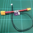
Then you are left with 4 wires.
1 is ground, its green in my photos. The other 3 are you XY&Z limits.
These are connected to one side of your normally open limit switch. The other terminal of the limit switch is connected to ground. So when the limit switch is depressed, it will short the circuit to ground and the controller will know its at the ...limit.
Please note, grbl v.09 has moved one of the limit switch pins!! https://github.com/grbl/grbl/wiki/Connecting-Grbl
Also note: I have been pulled up on my resistance to adding resistors: http://www.shapeoko.com/forum/viewtopic.php?f=4&t=...
Step 3: Testing Your Switches
Some tips to help test without breaking anything!
Setup Grbl Params:
$20=0 (soft limits, bool)
$21=1 (hard limits, bool)
$22=1 (homing cycle, bool)
$130=XXX (x max travel, mm) Make YYY something larger than the machines travel
$131=790.000 (y max travel, mm)Make XXX something larger than the machines travel
$132=110.000 (z max travel, mm)Make XXX something larger than the machines travel
You Can test the limit switches by setting $10=16 (status report mask:00010000)
Then turning on Verbose logging (checkbox) on UGS.
You will see a stream of numbers like "[verbose]"
When you hit the Z switch (manually with your finger) it should change to "[verbose]"
When you hit the Y switch (manually with your finger) it should change to "[verbose]"
When you hit the X switch (manually with your finger) it should change to "[verbose]"
and off course if you have enough hands to push all switches it will show "[verbose]"
So of these 3 numbers, the first corresponds to Z, next Y and third X (seems a bit backwards so be careful) If you find that any of the switches are showing a different differently on the output then you need to swap some of the leads around so that it shows correctly.
Once you are done with this you can set the $10 back to 3 (you must do this or things dont work correctly) and at this point try a homing cycle - its the button labelled $H
Might be a good idea to first turn down the homing speeds:
$24=25.000 (homing feed, mm/min)
$25=250.000 (homing seek, mm/min)
Once you have validated the homing is all working in the right way you can turn them back up a bit.
Its nice to have them turned down while testing so you have time to hit the Estop if things are ging wrong, like for example the machine starts homing in the wrong direction!
You need it to home towards the limit switches. If its not going in the right direction you will need to mess with the $23=0 (homing dir invert mask:00000000) parameter. More info on that here: Homing Directions


