

Introduction: FM Radio With Si4703 Breakout Board, LCD and Arduino


This project is just a small part of a bigger project I have been working on for the past couple of years (on and off). The background to this project is that a couple years back, I found a modern jukebox (iPod connection, AM/FM radio, CD player...) which had been dumped across the road from my house. The body was in decent condition but almost all of the electronics were damaged or missing. The only parts I managed to salvage were the LEDs on the front panels of the body. So I decided that I was going to do up all of the internal electronics to get the jukebox back up and running. One part of this was to make an FM radio with a LCD and push buttons to control the frequency tuning. After some research, I came across this cool little breakout board that you could use with Arduino to make an FM radio. So here's what I've come up with! Apologies if some of my photos are a bit confusing and colours of wires don't match up exactly with what I've written; I did this project some time ago and made a few changes recently so I've got a mix of old and (mostly) new photos.
Step 1: Sort Your Parts Out
Here's what you're going to need:
Tools:
Soldering iron
Hobby knife
Side cutters/wire stripper
Materials:
Si4703 breakout board http://core-electronics.com.au/sparkfun-fm-tuner-e...
Logic Level Converter http://core-electronics.com.au/logic-level-convert...
Speakers or headphones
3.5mm male to male audio cable (only if connecting to speakers)
Arduino Uno http://core-electronics.com.au/arduino-uno-r3.html...
16 characters * 2 lines LCD http://core-electronics.com.au/standard-lcd-16x2-e...
2* N/O momentary push buttons
2* 100 kohm resistors
1 * 220 ohm resistor
Veroboard http://core-electronics.com.au/stripboard-small.ht...
Wire
Solder
Step 2: Solder Individual Wires to the Si4703 Breakout Board
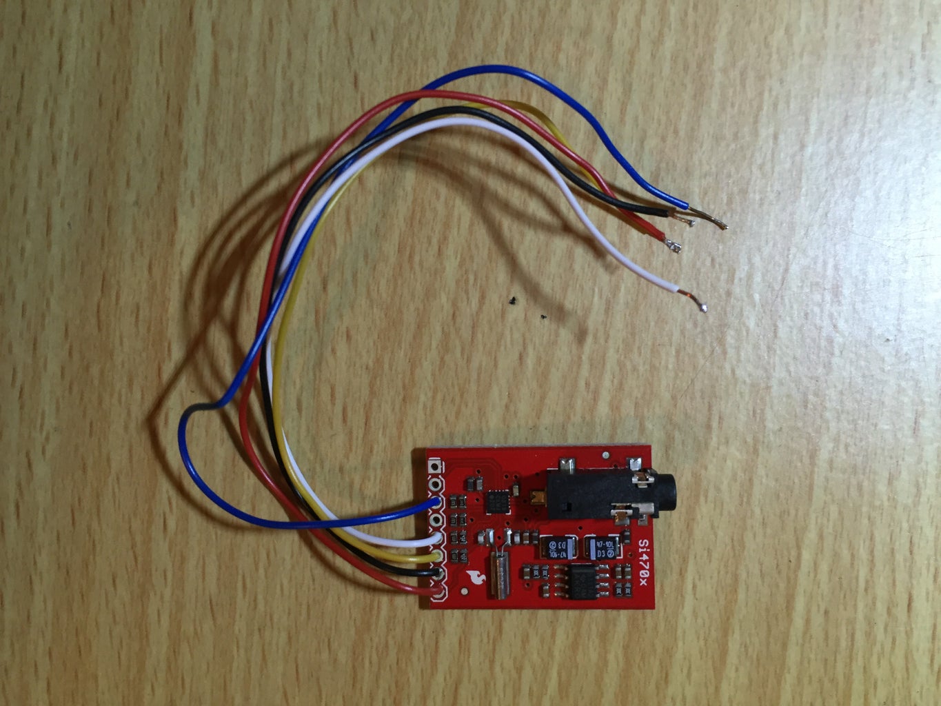

Solder some wires directly to the Si4703 breakout board. These are the pins that you need to use for this project:
- GND
- 3.3V
- SDIO
- SCLK
- RST
As always, colour coding these wires is good practice.
Step 3: Connect the Logic Level Converter Board to the Si4703 and Arduino

The Arduino Uno has a 5V logic level, and while the Si4703 IC is tolerant up to 5V, the communication pins are only 3.3V tolerant. A logic level converter (LLC) board should be used to connect between the Arduino and the Si4703; just to convert that 5V down to 3.3V so you don't damage the Si4703 IC. If you're looking for more information about how the board works, this tutorial has the details: https://learn.sparkfun.com/tutorials/bi-directional-logic-level-converter-hookup-guide
Here's how you should connect the LLC to the Si4703 and Arduino:
HV to 5V from Arduino power bus
LV to 3.3V from Arduino power bus
GND's to GND's
HV1 to Arduino analog pin 4
HV2 to Arduino analog pin 5
HV3 to Arduino digital pin 2
LV1 to Si4703 SDIO pin
LV2 to Si4703 SCLK pin
LV3 to Si4703 RST pin
Step 4: Get the Si4703 Up and Running With Serial Comms

In this step, we will follow the instructions given on Sparkfun to get the board connected to an Arduino and controlling volume/fm radio stations with the Arduino serial terminal. The tutorial can be found here: https://learn.sparkfun.com/tutorials/si4703-fm-ra... but I'll summarise for you.
Once you've sorted out your hardware connections, connect the Arduino to your PC via the USB cable and ensure that you have both the correct board and COM port showing up in the Arduino IDE. Connect the output aux from the breakout board to your speakers via an aux cable (or headphones) so you can hear if the radio is working or not.
Next, you'll need to download the Si4703 library from Sparkfun, available from this link: https://cdn.sparkfun.com/assets/learn_tutorials/2... Once you've downloaded this and added it to your Arduino IDE library, upload the attached code to the Arduino and open the serial terminal. (This code is under the Si4703 examples folder too).
You should now be able to play with tuning the radio module, changing the volume as well as setting some favourite channels through the serial comms. So if you've got all this working, you're to start controlling the board via push buttons and implementing the LCD.
Attachments

Step 5: Check the LCD Data Sheet for Pin Connections

I bought my LCD from Jaycar but they have stopped making this exact LCD so I'm glad I got the pin connections off the data sheet before they got rid of the product and all online information! Figure out from the data sheet which pins you'll need to connect in order to display some information using the Arduino.
For this LCD application, I only needed 4 data bits so the other 4 are not connected (for displaying text on a 2x16 LCD screen, you can do almost everything in 4-bit mode). The other connections are shown in the image.
Step 6: Connect the LCD to the Arduino Via Breadboard


Keeping the Si4703 breakout board connected, and using the pin connections from the previous step, connect the LCD to the Arduino. I first connected mine via a breadboard to get the first prototype working. In series with the backlight power V+ line, I have connected a 220 ohm resistor, this is used to power the backlight of the display and is a pretty standard connection for your LCD backlight. Unless you want to control the contrast of the screen via a potentiometer, this should be the only external component you need to connect to the LCD.
To use the LCD, you'll have to use the LiquidCrystal Arduino library which is one of the standard libraries that comes installed with the IDE. This library is used to control LCD displays that are compatible with the Hitachi HD44780 driver. More information about LCDs with Arduino can be found at this webpage: https://www.arduino.cc/en/Tutorial/HelloWorld
To make sure that your LCD works and is connected properly, you should run the 'Hello World' sketch as shown in the linked tutorial above. You can access this example by opening the Arduino IDE, navigating to 'Examples'>'LiquidCrystal'>'HelloWorld' as shown in the image. After running this and if you're satisfied with the functionality of your LCD, you're ready to connect the momentary push buttons to the Arduino and start coding for the radio.
Take your two momentary push buttons and solder 2 wires to each of them. Connect one side of each button to +5V and the other side to pins D10 and D11 with a 10kohm pull down resistor on each - if you're not sure what I'm talking about here, take a look at the connection in this tutorial: https://www.arduino.cc/en/Tutorial/Button. This is so that when you push the button, you can detect a high level logic at the input pin and change the frequency of the station either up or down depending on which button you press. Make sure that if you connect to +5V for the logic level that the Arduino you use matches this logic level. For example, some Arduinos a have a logic level of 3.3V, so if using a board with this level, connect the push button to +3.3V instead of +5V (Arduino Uno is +5V logic level).
As I did this project some time ago and took most of these photos then, I have no idea why I would have connected an LED to the breadboard in some of these pictures... Just ignore this as the LED is not present in the final version.
Once you've connected all the hardware, it's time to have some fun with the programming side of things.
Step 7: Arduino Coding
This code I wrote is fairly straight forward. When you turn on the radio by connecting the Arduino to power, the radio is tuned to a set station of which frequency is displayed on the LCD along with the words "FM Radio". From this point, you can use the tuner+ or tuner- momentary push buttons to find the desired station and watch it update on the LCD.
As I have several audio inputs to my jukebox, I decided to have the Si4703 breakout board set to a certain volume level and I could adjust the volume level of my speakers using push buttons on the front panel of the jukebox next to the tuner buttons. You can easily add a couple more momentary push buttons to the Arduino to control the volume level of the radio module itself though.
So I think that's the basic functionality of the code explained, the actual Arduino code is attached here.
I have read that the breakout board is also able to obtain other information such as song names, but I haven't found much more information regarding this and whenever I tried the RDS, nothing happened. For an update of this project it would be cool to remove the line "FM Radio" from the LCD and replace it with the name of the song that is currently playing. If anyone knows how to do this or can share some information, I'd love to hear from you!
Attachments
Step 8: Make the Connections Permanent


In this step I used a prototyping shield for Arduino to connect the Si4703, Logic Level Converter, LCD and push buttons to the Arduino. Simply transfer your connections from the breadboard onto the shield and solder them in.
After this, I made a little mount to fix the display and Arduino into my jukebox which conveniently already had a clear plastic window at the front. Depending on what you plan to do with this radio though, your mounting method could be quite specific so I'll leave that up to you guys to sort out!
Step 9: Enjoy Your New FM Radio!


Mine looks pretty glorious! Hope yours does too!

Participated in the
Arduino All The Things! Contest


