

Introduction: FTC - Encoder Cables for AndyMark NeveRest Motors


We are Cougar Robotics 4251 and this Instructable shows you how to complete the AndyMark Encoder Cables for your NeveRest motors and HiTechnic Controllers.
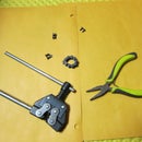
Step 1: Parts


- AndyMark AM-2965 cables
These are the double ended cables where both ends have the AndyMark motor connector on them. You can make two motor encoder cables from each one of these.
http://www.andymark.com/product-p/am-2965.htm - Digi-Key Conn Housing 609-2396-ND
This is the black connector housing that mates with a HiTechnic motor controller. It even has the little tab on it so that you always insert it the right way.
http://www.digikey.com/product-search/en?x=21&y=9&... - Digi-Key Mini-PV Crimp Wire rcpt 609-3620-1-ND
This is the receptacle that goes in the above housing.
http://www.digikey.com/product-search/en?KeyWords=...
Step 2: Tools


- Digi-Key Crimp Tool WM9999-ND
This is the Digi-Key crimp tool we bought just for doing encoders. We use the 1.6mm crimp spot for these connectors.
http://www.digikey.com/product-search/en?KeyWords=... - Wire Strippers
- Diagonal Cutters (these need to be good cutters to get a square end on the receptacles)
- Needle-nose Pliers
- Soldering gun
- Hot-glue gun
- Third hand clamp
Step 3: Cut Your Wire


The AndyMark cable comes with both ends set up for motors. Depending on the lengths you need you can get 2 finished encoder cables out of each AndyMark double-ended cable you buy. You can make one really long encoder cable by cutting off the white connector on one end. Or you can make two medium length cables, or one long and one short depending on where you cut the wire.
Step 4: Strip the Ends


Strip the last approximately 3/8" of the wire. This will give you room to twist, tin, and trim the ends of the wires.
Step 5: Tin and Trim the Stripped Ends


Twist the strands of the wires together. Then tin them. Using a good solder with flux, heat the wire so that the solder flows through the strands. You don't want any excess solder, just enough to bond all the strands together. When you are done tinning, trim any excess wire off such that the exposed tinned ends are about 1/4" long.
Step 6: Prep the Receptacles


The receptacles come in a long strip. Cut 4 of them off, and remove the feeding eyes (those are for the feed on machinary to automatically build these kind of cables). Make sure the end that will be inserted into the housing is "square". When cutting them apart it is easy to leave a little tab of extra metal on that one side of the end. (see the left end of each receptacle in picture 3) That tab can keep them from inserting properly into the housing.
Step 7: Crimp the Receptacles


Insert the large end of the receptacle into the 1.6mm jaw of the crimping tool. Line up the end of the wire with the end of the crimp section of the receptacle. Make sure to leave the gap between the crimp section and the tube section of the receptacle free of wire so that it will snap into the housing correctly. Then crimp the two triangular tabs around the tinned wire.* Then crimp the normal wire crimp section around the end of the tinned wire.
* The triangular tabs are designed to be crimped around the insulation of the wire. However, if you do that with the AndyMark wires then they won't fit inside the housing. So, instead crimp them around the exposed tinned wire.
Step 8: Insert Receptacles Into Housing


Insert the receptacles into the housing. Use needle-nose pliers to squeeze the tabs back down to lock them in. With the tab up the wires should be yellow, black, green, red from left to right as in the last picture.
Step 9: Hot Glue the Wire/housing Joints


Add hot glue where the wires go into the housings for strain relief. This makes the encoder cable much more rugged.


![Tim's Mechanical Spider Leg [LU9685-20CU]](https://content.instructables.com/FFB/5R4I/LVKZ6G6R/FFB5R4ILVKZ6G6R.png?auto=webp&crop=1.2%3A1&frame=1&width=306)


