

Introduction: Fighter Robot Gizmo | Robowars | Battlebot


Hello Dear Reader,
Here is our robot "Gizmo". It has two main functions to destroy their opponents in the battlefield: Flamethrower and Blender. This robot was built for robotics competition. Try your best to win the fight.
Check out our robot's video on youtube. If you want to see more robots, don't forget to subscribe.
Let's start with parts list for building this robot.
WARNING:
- This robot is not a toy
- Not suitable for in house usage
- May cause severe damage and you may burn yourself
- Operate this robot from far distance(3m at least) and don't connect its flamethrower and battery unless its inside the battle area.
- It is your responsibility to protect yourself - your robot building area - environment and other people.
Step 1: Parts List


In the pictures of this step you can see some of the parts. Basically we will need lots of parts and tools. But no worries. Follow the steps and you will finish building this robot.
Parts:
- Plated steel slotted angle.(2mm thickness) (3 or 4 meters long in total)
- 50x55cm aluminum sheet (1.5 mm thickness)
- Self Locking Metric 8 bolts (50 of them will be good enough)
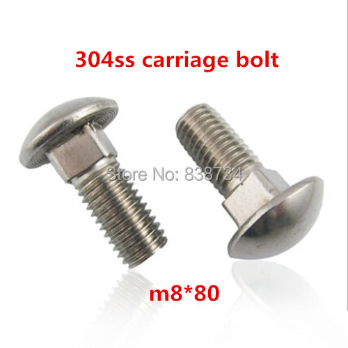
- Mushroom-head carriage bolts.(for Metric 8 size and with the length of 2cm at most) (50 of them)
- 2 metal freewheels with treads on it. ( Diameter of treated part is M8)
- 2 tires with high friction - Diameter of my tires are 13 cm and their thickness with the rim is 5 cm.
- 2 iron rod (45 cm long and has the diameter of 12 mm)
- First gear of any bicycle (Quantity: 2)
- Fifth gear of any bicycle (Quantity: 4) (you can change it in the way you want)
- 6 ball bearings with inner diameter of 12 mm and outer diameter of 28 mm
- M4, 8 cm long star head fasteners and their bolts (Quantity: 12)
- External retaining rings (Quantity: 20)
- L shaped wide metal brackets (Quantity: 7) (width near 7cm, long side length near 10 cm) (no exact dimensions. Check step 5)
- L shaped narrow metal brackets (Quantity: 2) (width near 5cm, long side length near 7 cm) (no exact dimensions. Check step ?)
- 3x 385 rpm motors with core of 10800 rpm
- 2x Bike Chain - Standard adult bike chain length will be enough
- 3x Unpolarized capacitors with 100uF If they don't work with your motors use 100nF instead
- Multiple sockets (male-female) - You can decide on them when you are reading the steps
- 2 m long fire resistant cable with 2 core wires
- 30 cm long fire resistant cable with 4 core wires
- 12 philips head M4 25 mm long fasteners
- Android Tablet
- M3 with the length of 4 cm with corresponding bolts (Quantity: 9)
- M8 Washers (Quantity: 6)
- HC06 Bluetooth module
- Arduino Uno
- Zip ties
- Arduino upload cable
- M3 set screws (Quantity:10)
- Kitchen Lighter with adjustable metal neck
- Kitchen Lighter
- 20 cm long plastic pipe (diameter depends on your butane tube's mouth)
- Pressurized Butane tubes (300 ml)
- Gas pipe claws (diameter depends on the diameter of your butane can)
- RC servo (9kg/cm)
- RC servo (12kg/cm) high speed with titanium gearbox
- Fishing string (30 cm is enough)
- Li-Po 11.1V 6000mah
- WP 1040 Brushed motor driver water proof (quality:3)
- Steel pipe diameter 5.6cm and length: 30cm or 20 or 25
- Primary shield -> metal sheet 3 mm thick hard iron 50cm x 24cm
- Secondary shileds -> 2 mm thick aluminum sheets. Size depends on your structure. Check the step named:shields
- Foams for shock absorption - to decide amount see the pictures at the step named: preparing li-po box
- Mushroom head emergency button (cuts the connection when its pushed)
- Plastic fire resistant boxes
Before you buy these part please read all the steps and decide on your dimensions. Because you may want to change dimensions and you may find a mistake in somewhere (I am a human :)
Tools:
- Powerful hand drill (for screwing and drilling)
- Different size of drill bits (for steel and aluminum)
- Soldering machine
- Pliers
- Side cutter plier
- Li-po Charger
- Files for metals
- Spanners (different sizes)
- Hack Saw or any automatic saw for cutting aluminum
- External retaining ring attachment tool
- Chain assembly tool
- Hot glue gun
- and anything you can think of as a need
Softwares needed:
- AutoDesk Inventor
- Arduino programming software
- Android device programming software
Step 2: Building Base of the Chassis


Let's start with putting together our very first rectangle for this robot.
You will need L shaped rough metal profile with holes on it. You can see them in the first picture. It is called plated steel slotted angle.
Check the dimensions of the rectangle in the second picture. Our dimensions are 65 cm by 50 cm. But don't screw them yet.
After cutting two pieces of 65 cm and 50 cm L shaped metals (in total 4 parts) You must prepare your bottom plate. This piece is 1.5 mm thick aluminum sheet. Its dimensions are 50cm by 55 cm. See the third picture.
Now, it is time to identify the places of tires. According to your tire diameter cut the rectangular places from your bottom plate of your robot. I am not giving the exact dimensions for this because it depends on you. Decide where you want to put your tires. What I suggest is put them away from blender part. Check the fourth picture to understand which side is front. In the front part of our robot, I placed blender and in the back part of the robot I placed flamethrower.
After you cut it, now it is time to assemble the avengers :)
One important note. You need to put a 2 cm offset from the back side of the robot. I marked them with red circle for you in the fifth picture.
With this knowledge in hand, assemble the base of our robot. You will need self locking bolts (for Metric 8 size)(see the sixth picture) and mushroom-head carriage bolts.(for Metric 8 size and with the length of 2cm at most) Check the seventh picture to see where you should drill and insert the fasteners (I marked them with white circles).
One final touch is to cut a space for our chain drive blender. See the picture 8 to understand what we are going to end up with by this cut. Accordingly open a small space by looking at picture 9. You don't need exact dimension. If you want, you can figure it out by looking at the holes on L shaped metal.
Know your base of your chassis ready. We will built everything on top of it.
Lets move to next step...
Step 3: Inserting Freewheels


Now it is time to start inserting our tires. I will start by putting the very small freewheels.
You will need metal freewheels with treads on it. See the picture of them. Diameter of treated part is again M8
Insert them into our base as you see in the second picture. And fasten them with self locking nuts.
Step 4: Preparing the Driver Tires


To make our robot move smoothly this step is significant.
You can see my tire and some parts in the first picture. According to your tire decision the part you need will change. Basically my diameter of my tire is 13 cm and its thickness with the rim is 5 cm.
We need to connect these 2 tires with the iron rod we have. Our rod is 45 cm long and has the diameter of 12 mm.
Additionally we are using first gear of an any bicycle. We designed two aluminum parts to hold this gear and to hold bearings.You can download our part designs. It is included in this step as an attachment. We used software called inventor to design them. By using same software you can open these files. You can see our parts in the second and third pictures.
We used 2 ball bearings per tire with inner diameter of 12 mm and outer diameter of 28 mm to connect our tire to our iron rod so that tire can turn smoothly.
To summarize, we stabilize our tires with ball bearings on our iron rod. Then we encapsulate them with our aluminum parts, and screw them together with M4, 8 cm long star head fasteners. See the pictures 4-5-6-7.
While plugging the tires into rod don't forget this: Gears should look outside the rod.
As a final touch in this step, we put external retaining rings (picture 8) to avoid our tires to slide left and right on top of the iron rod. With your hacksaw open small channels on the iron rod to plug these rings according to your tire positions. See the pictures 9-10-11.
You should open 4 channels at this step to stabilize tires on the rod.


Step 5: Attaching Driver Tires Into Base of the Chassis


In this step you will need two L shaped wide metal brackets.
Take them and open one hole in each of them. These holes must be symmetric on both of them and these holes will carry our iron rod. In picture one you can see two holes on them. Reason was to adjust height. But one hole is enough for you. Adjust your height and open the holes. (You will need to shorten one side of the L shape)
You will connect these brackets as you see in the picture 2. Which means that you need to open two more holes.
After you finish opening three holes per bracket, first fasten your brackets into base. They must be symmetric.
Now as you do in the previous step use retaining rings to stabilize iron rod on the chassis. Open the channel for these rings as you see in the picture 3. Then put first rings as you see in the picture 4.
After that connect rod that carries our tires into bas of the chassis. As final touch put retaining rings on each side of the brackets as well the make it safe.
Let's move to next step... it is time to connect motors
Step 6: Placing Our Driver Motors and Chain Connection


Check out the video at this step to see how it is going to be like when our system starts to work.
Before you start implementing this step. Read all the way through the end of this step. You may want to change somethings.
First of all take one of L shaped brackets and place it near to your tire. You should do this placement according to your motor dimensions and your chain length (read whole of this step before you start) . And open holes on your bracket to mount motor on it and also to mount your bracket on to our chassis. Don't forget to open same holes on top of your chassis as well. (dimensions of these holes depends on you - I suggest M4) See the pictures 1-2-3. I also used wooden block to elevate my bracket. If you use long enough L shaped bracket, you will not need it. See it in the picture 4 (use the same brackets from the previous step)
It is time to mount our motors.
Let us meet with our motors. See them on pictures 5,6 they are 385 rpm high torque motors. Unfortunately provider didn't gave any info about their torque value but you can check it by observing output of 385 rpm from 10800 rpm core proton motor. I suggest you to use more powerful ones.
Take one of the unpolarized capacitors with 100uF and solder it in between + and - edges of the motor. See the pictures 7-8 also take some sockets for easy plug in and out, solder them into the edge of at least 25 cm fire resistant cables. And other edges of the cable must be soldered into our motor. Remember the colors for + and - See the pictures 7-8
if you don't solder capacitor in between them, your motor driver will stop working and you won't be able to move the robot.
Now mount the motor into bracket. See the pictures 9-10. The fastener dimensions will change according to your motors requirements. I used 4 philips head M4 25 mm long fasteners per motors.
To connect our gears into our motors, we designed a part. You can see it in the picture 11 and we used fifth gear of any bicycle. You can change this gear as you want. See it in the picture 12. You can use different gear as well but don't forget to change the design that we provide. And before you buy a bike gear check the correct dimension according to our drawing.
See our drawing in the attachment (its name is motor but it is not a motor :D just a name) You can open with software called inventor
Connect our designed part and bike gear with fasteners. we used M3 with the length of 4 cm to fasten them with corresponding bolts. You may want to change the length, it might be a bit long. Check it before you proceed. You can see assembled gear at pictures 13-14
At picture 15 you will see that we added two washers before we connect our gear assembly into motor mil. These washers are M8. You can reduce their size according to your motor mil.
It is time to connect our chain. To do that you need to correctly measure the length. Because you want your chain to be as tight as possible otherwise you may lose it in a crash in the battlefield.
Due to this fact prepare your chain length at the very beginning of this step while your are arranging the distance of your bracket from the tire.
See the pictures 16-17-18-19-20-21 for how its going to be look like.
Don't forget to stabilize gear attached parts into motor mil via setscrew or retaining rings
Step 7: Weapon#1: Flamethrower Mechanism


Check the video of this step and see how well the flamethrower is working. But you will notice that the power of our motors are not that much sufficient. You should increase the torque in your design.
Let's build the flamethrower!
First take a kitchen lighter and take it apart. We need its long neck. See the picture 1 and stabilize that neck in the middle of our robot's back part with small width brackets that we have. Our plastic neck must have metal nose otherwise it will melt. Stabilize it with using hot glue gun on to your brackets. And stabilize your brackets into our base chassis with any fasteners you want. See the pictures 1-2-3-4 Then take a 20 cm long plastic pipe in the diameter of the nose of your butane gas holder tube. Plug an metal hollow cylindrical object into the mouth of your pipe (see pic5) and plug it inside your stabilized mechanism as you see in pic 6.
It is time to put butane carrier. With our mushroom head M8 bolts we stabilize the clamp for our butane can. Then we use the clamp to hold our butane can. See the pictures 7-8-9. Arrange the place of your butane can according to pictures. In the pic 10 you can see my butane cans.
Now I will introduce first servo motor for this project, to operate follow of butane. This servo must provide at least 9kg/cm. Otherwise you won't have enough force to operate it. Our system to get the gas out of the can is very basic. it operates like a door. See the system in pictures 11-12-13-14-15-16-17-18-19. It is easy to understand my steps by following these picture with the order that I provide. You door system must have a long column and door and servo arm to open and close the door. The door that I am talking about can be seen in pic15.
After you finish this door mechanism, you can connect plastic pipe into butane can (pic 20) and try servo with your hand to see that butane gas is flowing nicely from your pipe. (It is flammable you know!!!)
Now take the pipe out from the can and cut the connection for safety. Because we will introduce spark trigger mechanism to create flame.
Take one more kitchen lighter with a metal and adjustable neck and dissemble it. The part we are looking for are shown in the pictures 21-22-23.
Take the spark producer and put it inside the wood stabilizer. See the pictures 24-25-26-27
Two cables from the spark producers will come out. They shouldn't touch each other. When the spark producer triggered the spark will jump from one cable to other. I assume that you know a lighter works. So that take these cables and by looking pictures 28-29-30 arrange them.
It is time to introduce our second powerful servo motor with high speed titanium gearbox and 12kg/cm. See the pictures 31-32-33-34 to stabilize them accordingly.
Let's stabilize the metallic neck into our chassis for being our pilot flame producer. See the pictures 35-36-37.
After that we need to stabilize our small gas tank for pilot flame. See the pictures 38 and 39. I used fishing string for opening the valve of this small gas tank. It is tied to arm of our servo. When servo turns in the clockwise direction it will trigger the spark producer and at the same time it will release the gas from small tank so that our pilot flame will appear. In our computer program for this robot we will first operate pilot flame and thence will leave the butane gas from the container tank.
As a final step cover the small cables and servo cables and other flammable things with aluminum foil. See the pictures 40-41-42-43-44
Step 8: Weapon#2: Blender Mechanism


Take our second iron rod and open channels for retaining rings as we did before. And put two bearings on the rod. See the pictures 1 and 2
Then take a steel natural gas pipe and cut it in the any dimension you want as your blender size we used 30 cm. And attach aluminum blocks on it. We used Al7000 series to be hard. See the picture 3-4-5.
In the picture 5 you will notice that we opened set screw hole at the edges of our steel pipe to stabilize it later.
After that you will remember our parts that we design to hold our tires. Reproduce them to hold our weapon. see the pictures 6-7-8. One with the gear on it and the other without gear. Also open setscrew holes as same with the steel pipe.
Then concentrate on picture 9 and 10. With the same order stabilize the both ends. See the final look at picture 11 and 12.
Let us connect our iron rod into our chassis as we did before. See the pictures 13-14-15
As a final step we need to decide on chain length and mount our motor. Again by following the same steps as we did in driver motors, mount your blender motor into your chassis and decide chain length and connect them. Remember the gap we create on chassis at the very first steps ? The chain will be place in to that gap. Don't forget to solder capacitor ! And See the pictures 16-17-18-19-20-21-22-23
Don't forget to stabilize gear attached part into motor mil via setscrew or retaining rings
Step 9: Cable Connections Flow Chart

See the flow chart and understand it.
This is how we are going to connect our cables inside our robot. If you have any questions. Comment below and ask me.
Step 10: Preparing Control Box for the Robot


Inside our control box don't but LiPo and HC06 bluetooth module. Rest will be inside.
See our motor driver units. WP 1040 brushed waterproof motor drivers. Place 3 of them inside our plastic fire resistant box. Glue them into inner walls of our box. See pictures 1 and 2
Put Arduino inside our box and stabilize it. Make connections (pic3) and mark the cables (which one is which ?)
Then allow cables of bluetooth module to go out of the box from the roof. And the cable goes out from the roof must be fire resistant with 4 inner cores. Also put upload switch on the roof as well. See the picture 4-5
Then all the cables that are going to connect Lipo, servos and motors should go out from the side of the box. See the pic 6-7-8 and plug arduino programming cable as well.
Place the box on top of our chassis and stabilize it with fasteners. See pictures 9 and 10
Step 11: Preparing Li-po Box


We are using 6000 mah 11.1V Li-Po battery.
You need to protect it as much as you can.
Take the one more hard plastic fire resistant box and cover inside of it with foam.
Put mushroom head emergency button on the roof of the box (when button is pushed connection is interrupted)
Make the connection according to our flowchart
The wires goes out of the box must be fire resistant.
Your battery will be safe inside this box.
And stabilize the box on the chassis with fasteners as we did at the previous step.
Step 12: Shields


It is time to cover our robot.
Let's start with our primary shield. The tough one. It is out of 3mm sheet metal and had to drill.Measure it and buy it accordingly. Suggested dimensions are 24cm x 50cm
Open a flame hole in the middle and attach L shaped metals on the side so that we can connect it with our chassis. See the pictures 1-2-3-4
Then create the inner frame of our robot with L shaped metals. height of the robot is 15 cm. Check it and start building it. Fasten them together with our M8 Mushroom head fasteners and bolts. See the pictures 5-6-7-8-9-10
Then insert secondary shields. These are our protectors but you should receive any damage from primary shield. avoid secondary ones. Secondary shields are from aluminum and they are light and 2 mm thickness. Cut them properly and insert them to sides. Pictures 11-12-13-14
For the roof you need to allow a small gap for some fire to escape. Don't close it too much. You need to allow the fire escape. Observe the gap in the picture 14.
Don't forget you will open and close it too much so don't connect the roof yet. You can connect it when you are in the battlefield.
Step 13: Installing Arduino Code
I guess you will love me a lot. In the attachment you can see the code and download it. Just make sure that everything is connected properly and you can change the code if a cable is connected to another pin.
*****************/////////////////////*******************************/////////////////////**************
Don't forget your butane gas pipe must be unplugged !!!!!!!!!!!
*****************/////////////////////*******************************/////////////////////**************
We are few steps away from making it work.
Upload the code. Don't forget the use upload with otherwise you will see an error.
Attachments
Step 14: Android Code for Control Panel

Here is your android code. Download it and unzip it and load it into your tablet or phone. I suggest use tablet.
I assume that you know how to upload android program into your tablet.
Control panel is designed for Lenova tablet. So it may appear weird on your device. You can change it by playing with the code.
Warning: Touch screen control is a big mistake. If I were you, I would use real control panel. (I am not repeating my same mistake)
In the video you can see that our robot is not able to move so smoothly. Because of touch screen sometimes you are having hard times to control. In the battle area you will be exited and touchscreen control maybe even more harder.
Attachments
Step 15: Ready to Fight ?


ENJOY using it on the battlefield.
Make better one and send me the pictures.
Don't forget to subscribe my youtube channel.
WARNING:
- This robot is not a toy Not suitable for in house usage
- May cause severe damage and you may burn yourself
- Operate this robot from far distance(3m at least) and don't connect its flamethrower and battery unless its inside the battle area.
- It is your responsibility to protect yourself - your robot building area - environment and other people.

Runner Up in the
Tech Contest

Participated in the
Robotics Contest

Participated in the
Arduino All The Things! Contest


