

Introduction: Firework Control Module


A few years ago I came across a firework control module built by Instructables user: systemf92. His module was a great design (found here) and I knew that I would one day have to build something similar because it combined two things that I really enjoy: Electronics and Blowing Stuff Up on Independence Day. Well, a few years passed and I finally decided it was time to build one of my own.
My module is Arduino powered for a few reasons. 1) I need to work on my programming skills. 2) I wanted it to be "smart" or "aware" of what connections were present. 3) I wanted to have control over timing adjustments that a more analog solution wouldn't allow. 4) I wanted a more graphical user interface that would be fun for my kids. The complete solution was a two part module that allows you, children, babies, etc to safely enjoy launching fireworks from a minimum distance of 50 feet. I wouldn't have felt comfortable sending my 3 year old up to a mortar tube with a punk, but I would let him launch them all day with this and its included safety features.
I tried to take pictures along the way in order to make a clear Instructable. I succeeded in some step and others I failed. But there is no way I am taking this thing apart for more pictures! Take a look through the Instructable, ask questions if you are curious and I hope you build some version of this for yourself!
Be sure to vote for me in any open contests.
***IF YOU ELECT TO BUILD SOMETHING SIMILAR OR DETONATE FIREWORKS OR OTHER EXPLOSIVES IN GENERAL BE SURE YOU DO SO IN ACCORDANCE WITH ALL SAFETY GUIDELINES AND LOCAL AND FEDERAL LAWS. JUST BECAUSE YOU CAN BUILD SOMETHING DOES NOT MEAN YOU KNOW HOW TO USE IT SAFELY. PROCEED WITH CAUTION AND NEVER USE FIREWORKS OR OTHER EXPLOSIVES AS A WEAPON, IN THE FORM OF A WEAPON OR TO CAUSE BODILY INJURY OR HARM TO AN INDIVIDUAL OR PROPERTY***
Moving on now! :)
Step 1: Plan Your Circuit

I wanted my fireworks controller to have the following features:
- Required a physical key to arm
- Have a display that could be read from 20+ feet away
- Fire up to 8 separate fireworks in one setup
- Be Arduino controlled
- Fit in a compact, weatherproof case
- Be "smart" in that it knows if there is a malfunction with one of the electronic fuses
- Have the ability to be controlled by a hand held remote
- Be usable by adults and children alike
- Have igniters be easy to repair or swap out on the go
- Have igniters that attached easily to different fuse types
- Look neat and professional at the end of the build
In order to accomplish all of these things I needed to do some careful planning and some research given that I am a rather amateur tinkerer when it comes to electronics. I hope to walk you through some of my thoughts/steps that I took along the way. Sorry if this is a bit long-winded, but I like to be as thorough as possible.
Attached you will see a picture that shows the general layout of the circuit as you would assemble it via a breadboard. Some things are just blocks of text due to Fritzing not having the components or the complexity of separate circuitry. I will do my best to describe everything and how it is interconnected.
Arduino - I chose to go with an Arduino Mega 2560 because of all the beautiful I/Os. I needed a lot for this project if I wanted to stay away from input/output shift registers because I don't know much about them. If I were to do this project again I could easily get up to speed on shift registers which would simplify wiring and allow me to use something more practical like an Arduino Uno. The sketch only required short of 8k so the Mega is "Mega" overkill. Likewise, if you wanted to build something with less firing nodes, you could likely step down your number of I/Os needed while maintaining a similar design. Or, if you wanted more firing nodes you could use shift registers and more relays to crank the number up to near infinite.
Isolation - Given that I am using an Arduino to drive high current ignitors I wanted lots of isolation. This added to the wiring but it makes me feel plenty safe that this thing will operate for plenty of time into the future.

Step 2: Parts List - Many, Many Parts


This parts list is quite extensive. I didn't realize how long it was until I started typing it all out. Based on your design you could omit some of these or potentially add more! Overall there are 45 different component types, multiples of many of them.
- 12V Lead Acid Battery
- 12V Battery Charger
- 6 AA Battery Pack
- Optocouplers
- 560 Ohm Resistors - 1/2W
- 10K Ohm Resistors - 1/4W
- 1.2K Ohm Resistors - 1/4W
- Ethernet Cables - 50 ft
- RJ45 Keystone Jack
- Keystone Plate - 3 hole
- Control Module Case
- Firing Module Case
- 10K Potentiometer - 1/2W
- Knob for Potentiometer
- LED Illuminated Buttons
- DIP Sockets - 16 Pin
- Key Selector - 4 position
- Power Switch
- Prototyping Boards - 5x7cm
- Prototyping Board - 4x6cm
- Arduino Mega
- 5V Regulator
- Nichrome
- Banana Plugs
- Banana Binding Posts
- Clothes Pins
- WS2812B LEDs
- Red LEDs
- Remote Control Module
- Relay Board
- Ribbon Cable
- Ribbon Cable Terminator
- Header Pins1/4"
- Acrylic - 12" x 12"
- 1/8" Acrylic - 12" x 24"
- Acrylic Cement
- Plexi Glass
- Window Transparency Film
- Foam Board
- #6 x 1-1/4" Machine Screw
- #6 Nuts
- #6 Cap Nuts
- #6 Washers
- Crimp on spade connectors
- Crimp on terminal connectors
See the attached PDF or picture for the full parts list including source and cost information.
Attachments
Step 3: Choose Your Cases


This design utilizes two cases. One case houses the Arduino and 90% of the circuitry and acts as the "brains" of the launcher. The other box houses the relay board, sealed lead acid battery and the "higher" voltage circuitry (12v).
Control Module Case - The Brains
The main considerations here are 1) that you can actually cram all your amateur wiring into the case and 2) that it provides for easy access to your buttons and finally 3) that it can hold any display that you put in place in a secure manner that is easy to see. Also, you want it to be made of a material that you can easily cut and work with for mounting and wiring pass through as needed.
I really liked the look of Pelican cases but they were generally $50+ and didn't have a recess in the lid that would work for my planned display. There were a few Monoprice cases that looked like they could work but they were also more than I wanted to spend. I ultimately found a Rakshak case for $29.99 on Amazon that had nearly perfect dimensions based on what I knew at that point in time of my project.
Firing/Relay Box - The Brawn
This case could be much more lenient as the is nothing to display here. Just a case to hold the components and have enough surface area to install all the connectors for the igniters. I had a spare Plano brand plastic ammo can that looked like it could fit the bill perfectly.
Step 4: Start Building
I chose to compete this build as more of a modular setup in which many different protoboards would take the place of one larger development board. This would benefit me in two ways. For one, it will help us with the build to make this all in pieces and connect it all together later with custom made connectors as it allows us to make more changes on the fly. This worked well for me because I was designing the project as I went. Secondly, it would help us to fit everything inside the case. If we put it all on one larger board it would be a difficult form factor to fit into our control module case.
As you can see by my original Fritzing diagram I split it out into many breadboards to better tie into my implementation. Each board serves a specific role, and that helps alleviate confusion once you are knee deep in wires, ICs and solder.
The main boards I split it into are:
Button read - Senses which buttons are being pressed
Button illuminate - Illuminates the buttons based on the PWM signal coming from the Arduino.
Remote Control - This is already a breakout board of its own.
Sensing nodes - This reports which firing nodes are connected and ready.
Power Regulation - This board regulates the 6 cell AA battery pack (9v) to 5v for running the Neopixels (WS2812B LEDs)
Power Distribution - Almost every board needs V+ and Gnd. This board merely contains pins to tap into the common ground of the circuit and 5v supply coming from the Arduino.
Step 5: Button Sensing Board


This board is about as simple as they get. It simply has a circuit for each button that contains a pull down resistor and connection to an Arduino digital pin for each button. Above you will see the Fritzing diagram associated with this board and a quick schematic showing the pull down resistor concept. I don't have a picture of the actual board itself, but that's probably for the better because the soldering is poor and you would be bored.
The resistor between Ground and the Arduino pin ensures that the signal seen by the Arduino when the button is not pushed is always low. I used 10K Ohm, 1/4 watt resistors for my pull down resistors. Any value about 4.7k Ohms or so should work well though.
Step 6: PWM Button Lights Board


Another quick and boring board. This is simply a set of current limiting resistors in line with the PWM pins from the Arduino. Nothing special. Fritzing diagram shown above along with a brief little schematic shown above for anyone who is not familiar. Resistors used were 220 ohm 1/4 watt. What resistors you use is entirely dependent on what voltage drop and current you want through your LEDs.
Step 7: Power Regulation Board


The display that I have designed for this runs off of NeoPixels (WS2812B LEDs). It is an easy way to create a simple custom display and I have used them in many other projects. They are very happy to run off of 5v and that's exactly what we will do here. They are, however, too power hungry to be powered by the Arduino's onboard regulator so we have to build a separate voltage regulation circuit to run in parallel.
Power Requirements
Using Adafruit's guidelines we assume a maximum current draw of 20mA per color. RGB LEDs have 3 colors giving a total current draw of 60mA per LED. This project uses 34 pixels to give a total maximum current draw of 34 * 60 mA = 2,040 mA. We will not be using near that much in this project as we will not be setting the brightness to maximum and we will be only using one color at a time. As you will see later in my code we only use colors green and red and we do not mix them on any given LED at the same time. So we can therefore assume each LED will consume approximately 20mA when lit. I also define the maximum brightness as 150 out of 255, while this is not linear on current consumption I have observed in the past that a brightness of 150 will generally consume about 70% of maximum. So now we are down to 20mA * 0.70 = 14mA per LED.
We take the conservative assumption that we need to provide power assuming all LEDs are lit (never does the software allow all to be lit) at the same time giving us 14mA per LED * 34 LEDs = 476mA. This is a much more manageable amount but is too much to tax the Arduino's onboard regulator with (500mA). But it is an application that we can easily handle with a LM7805 linear voltage regulator with no additional heat sink required. The LM7805 can safely dissipate 2W under normal ambient conditions and the calculation is a simple one. (Input voltage - Regulated Voltage) * Current in amps = Watts to dissipate. So in our case we have a 9v supply, 5v regulated with a 476 mA draw. So... (9v - 5v) * 0.476 A = 1.9W.
The remaining electronics in the project are all very minimal current draw and a sourced by the 5v bus of the Arduino.
LM7805 Setup
Due to my own ignorance I tried to set up the LM7805 by just supplying 9 volts in, Ground and taking the 5 volts out directly to my load. While my multimeter said all was good with this setup and I was getting a nice, clean 5 volts out as soon as I would put any load on the system the 5 volt supply would fail and behave erratically. After some quick research online I found that I needed smoothing capacitors on either side of the input and output voltage. The datasheets I found called for a 0.33 micro farad ceramic cap between 9v and GND and a 0.1 micro farad ceramic capacitor between 5v and ground. With those two in place the regulator worked beautifully.
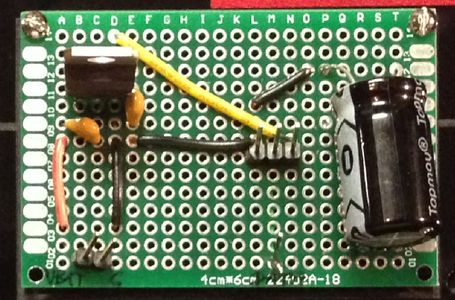
Other Board Components
There is a large electrolytic capacitor on the board connected between 5v and GND to smooth the power going to the NeoPixels. Adafruit recommends a 1000 micro farad cap here, but given we only have a small amount of pixels here I went with something much smaller as I have on many other projects. I think this is a 47 micro farad cap and it has worked beautifully.
There are three sets of pins you will also see on here. The first set on the bottom left is simply input of Vbatt and GND which supply the input voltage (9v) and GND to the LM7805. The next set is bottom middle and is a single pin, this takes the data signal from Arduino pin 22 and simply acts to pass it along to our next set of pins. The third set of pins (top-middle) is 5v (from LM7805), GND (common) and Data (from single pin described above) and this serves as a one stop three pin connector by which to connect the NeoPixels from the display as we are buttoning everything up on final assembly.
There are some wires running on the bottom side of the board here that you can't see but with the Fritzing diagram it should be clear how all these are wired up.
Step 8: Ignitor Sensing Board


Part of my plan with the controller was for it to be self aware of which igniters were connected and which were not. In order to do this it had to be able to pass a low current through the igniter that would not make it hot but at the same time would be able to alert the Arduino. Problem is that the igniters run off a 12v system and the Arduino runs off a 5v system. Connecting 12v to the Arduino is a no-no that may let out the precious magic smoke or burn out some digital I/Os. To accomplish this we use an Optocoupler.
Optocoupler explained
An optocoupler is a means to communicate signals from one logic level to another with complete circuit isolation. No voltage, current, etc from the 12v circuit can reach out and touch the 12v system. It accomplishes this by using an infrared LED / photo-transistor pairing. When the signal is HIGH on the LED side it illuminates the LED which shines directly across the IC (hidden in the package) and onto the photosensitive. The photo transistor then goes from a high impedance state to a low impedance state, essentially acting like a switch which gets turned on.
Circuit Explanation
When the igniter is not connected there is an open circuit on the IR LED side and thus no current can flow through the LED and illuminate it. When that happens the photo-transistor remains in a high impedance state (open circuit) and allows no current through. There is a 10k ohm pull up transistor sitting in place on the collector side of the transistor. With no closed circuit there is no current flow and thus no current drop across the 10k ohm resistor. Therefore the voltage on either side of the resistor is 5v and the Arduino reads that as a HIGH. According to the code HIGH indicates that there is no igniter connected thus it is not available for launch.
When the igniter is connected it allows a small current through to the IR LED which shines on the photo-transistor which puts it into a low impedance state (closed circuit / switch on) and the current can flow from 5v supply, through the 10k resistor, through the photo-transistor to ground. The 10k resistor is much higher resistance than the phot-transistor and has essentially created a mini-voltage divider of which 99% of the voltage drop occurs over the resistor leaving near 0v to be read by the Arduino. The Arduino reads this as LOW which the code tells it that there is indeed an igniter present and once armed the system will be happy to blow up bright, shiny firework goodness!
The Board
Once again some of the wiring is under the board so it may be slightly confusing but just follow the Fritzing diagram and you can't get lost. Start by soldering your 16 pin DIP sockets in place. These allow you to readily replace the optocouplers as needed should they become damaged through either physical abuse or more likely electronic ignorance.
Read the datasheet for you optocoupler to figure out what resistance value you need in place to satisfy the voltage and current limitations of your IR LED. I tried to go as high as possible on the resistor in order to limit current draw. I tested one channel of the optocoupler first to make sure it was happy to turn an LED on and off through the photo-transistor and then called it good. Solder you resistors in series with your IR LEDs and then solder the other end of the resistor to the pins for easy connection of the modules later. Include 1 extra pin off to the side in order to bring ground back to the 12v battery, remember, we are going for full electrical isolation, there need not be a common ground between the 12v and 9v or 5v power sources.
I kind of already described the setup of the Arduino side above. Essentially think of each photo-transistor as a switch with a pull-up resistor and you have it made. Run wires from between each photo-transistor and resistor to a set of pins on the side of the board for connection to the Arduino later. Include both 5v and GND pins here as you will need to supply it from your power distribution board later.
Step 9: Power Distribution Board

It doesn't get much simpler than this. All this board does is supply some parallel connections to both Vbat and 5v.
The top left shows two pins in which the battery would plug in. The red and black wires running across the board go to a barrel plug that supplies the Arduino 9v into its barrel jack where it is then regulated down to 5v for controlling the processor.
The top-rightish-middle pin is 5v back from the 5v rail of the Arduino. It then connects to the row of pins directly below which are used later in distributing 5v around to the other boards/modules. On the far right is a set of GND pins that just tap into the GND of the battery connection back on the far left. Ground is common throughout the Arduino, our battery and all other circuits that operate at the 5v level.
I drew the black vertical line on the board just to serve as a reminder that these don't mix!
Told you it was simple.
Step 10: On to the Firing Case!


Ok, we are done with all the modules from the control box, now onto the "dumb" part of the project. If you are wanting to make a simpler setup that just uses the relays to fire the igniters and use buttons, this is basically the place to start, or there are plenty of other instructables out there covering those setups.
In this box we will have:
Binding posts for connecting the igniters
Relay board for supplying high current to the igniters
12v sealed lead acid battery
Current limiting resistor to reduce amperage through the igniters
Board that collects the "sensing nodes" to send to the previously built optocoupler board.
5v regulation - on the same board as above.
On to the next steps to see how the Sensing node board goes together.
Step 11: Sensing Node Board (and Power Regulation)


This board primarily serves the role of gathering the sensing nodes and passing them on to the control box. It also contains 5v regulation circuitry for the 5v relay board to work. Attached are the two Fritzing diagram segments that illustrate what we are building on this board/module.
"Dumb Sensing Nodes"
In the Fritzing diagram that has the LEDs you can see the green wires coming in from the igniters. There is one green wire that I have actually drawn out all the way to an igniter to give you a better idea of how the circuit works. In this picture, the igniter is represented by the coil; Fritzing didn't exactly have a firework igniter in their parts library :).
The green wire ties into the igniter circuit on the downstream side of the Nichrome and then heads over to the breadboard. There it splits into parallel paths. One path goes through a current limiting resistor (560 ohms) and connects to a red LED. This red LED serves as a sort of sensor that lights up if the current path is complete. This is helpful if you are troubleshooting while away from the control box and are out near where you are setting up the show so you don't have to walk the 50' back and forth. The cathode of the LED returns to the GND of the 12v source. The other path goes to a row of 8 pins that will later go down and connect to our optocoupler board that we detailed earlier. There it illuminates the IR LED that passes on its status to the photo-transistor. GND comes back from the optocoupler board and to the 12v source's ground.
5v Regulation:
The relay board that we are using required 5v to fire the relays. I had room on this "dumb sensing node" board and didn't want to waste another protoboard so I squeezed this circuit in there. Same as the previous 5v supply built, capacitors and all.
Step 12: Prepare Your Firing Case


Begin to lay out your firing case for final assembly. All of our igniters will attach to the firing case via banana plugs which fit into stereo binding posts. This gives you the ability to plug in and setup quick and change out igniters as desired.
Lay out all of your binding post mounts on the side of the case. Keep them enough off the bottom that you will have room to work with future wiring and enough from the side that you will be able to fit you sealed lead acid battery in upon final assembly. I lined all mine up as straight as I could, used a rule to get them equidistant and marked the holes to be drilled with a sharpie. Remove the base plates and crack out the drill. Select the proper sized bit for your binding posts and drill all 16 holes. Metal bits cut through this plastic like a hot knife through butter!
Insert all of the binding posts and bolt them into place!
Select the location where you 3 hole keystone plate will go. Line it all up and then trace out the recessed portion with a marker. I then used a Dremel with a cut off wheel to cut the hole, cleaned it up with a grinding wheel and put the keystone jack in place. I marked the holes for the bolts, drilled them and mounting was complete.
If you want this case to be water resistant then you will want to apply silicone caulking or similar to the backs of your binding post base plates and keystone plate.
Step 13: Wire the Firing Case


This part is pretty simple wiring but as with any project it gets to be a mess in a hurry. I will walk you through it below and via the annotations in the pictures.
Relay Board
Connect all center terminals of the relay together in parallel as shown in the to pictures of the relay board. Then run this wire to your 3 ohm, 50 Watt resistor. This way when the relay is triggered the resistor will add significant resistance over and above the resistance of the Nichrome wire. It turns it from a 1/2 ohm load to a 3.5 ohm load. This greatly reduces the current supplied by the lead acid battery which should extend its life and extend the life of each nichrome ignitor. We move from dropping 12 volts across the Nichrome to just under 3 volts. This results in a current drop from 20 amps to just under 2 amps.
Connect one red wire from each relay's Normally OPEN terminal and connect it to the black binding post. I used crimp on terminal connectors to make this connection easy. I also snuck the node sensing wire into the crimp to simplify my wiring later on.
Supply 5v from the 5v power regulation circuit to the relay activating portion of the relay board (on the skinny side). Connect ground from this as well (common ground really).
Binding Posts
As described above, you will connect the red wires from each relay to the corresponding binding post (black one). To supply voltage to the circuit I stripped the insulation off of a piece of copper wire and connected all of them in parallel. This wire then connects to the V+ terminal of the 12v lead acid battery.
Resistor
The 3 ohm, 50W resistor connects in series to the black wire leaving the relay board's center posts and then to the Ground terminal of the 12v lead acid battery.
Sensing Nodes
The wires for these were connected to the crimp on terminal connectors back when we walked through the relay board connections. We simply take these now and connect them to the header pins we previously soldered on the "dumb sensing node" board. Connect each of them.
All connections are now made. You can also include a power switch as I have shown in my Fritzing diagram. Just wire it in series with ground right before the ground terminal.
Step 14: Build the Firework Control Board


Not we are ready to build the control panel for the "Brains" of the launcher. I chose to make my panel out of acrylic. I downloaded all of the datasheets for my components (mostly from Jameco) and all the buttons, keys & switches had dimension labeled drawings for panel mounting. I translated those dimensions into Inkscape, measured out where my panel would go within the case and drew everything out. I also drew templates for legs to hold the panel off the bottom of the case and a "shelf" of sorts that would hold all of the modules/boards. This way the whole control panel with brains attached would easily lift in and out of the case together.
Control Panel
This is designed and cut out of 1/4" black cast acrylic. I went with 1/4" to make sure it was sturdy enough to withstand button presses, the torque of the key selector turning and general abuse from my over-excited children. Labels above each button, switch and knob were drawn to laser etch them into the cast acrylic. I cut this out on an Epilog Mini 40W laser cutter at my local FabLab.
Legs
I took careful measurements that such that once all buttons were mounted and the display screen was attached that there would be enough room to close the lid while still keeping the control panel sitting as high as possible. To aid in final construction and layout of the electronics I attached several of the control boards to the legs as well.
Shelf
This is where the brains of the operation lie. I measured and designed holes for attaching the components (Arduino, protoboards, etc). Then I created raster shapes to etch the acrylic with the laser as to where each board went. This really helped with the final construction.
Assembly
I used acrylic cement to clue the legs to the bottom of the control board. Small machine screws and nuts to hold the shelf onto the legs loosely and #2 machine screws to hold many of the components, boards, etc onto the legs and shelf.
PDFs attached, ready to send to the laser cutter.
Step 15: Creating the Display Screen


I wanted a nice display screen for the launcher so that anyone enjoying the firework show could see what nodes were active, the countdown and if the device/launchers were safe to approach. The whole thing needed to be large enough to read from a distance, be easily controlled from an Arduino and look professional. I have experimented with NeoPixels (WS2812B RGB LEDs) with some of my other projects (posted to Instructables, check them out!) and they turned out to be the perfect fit for my application. Best of all they would only required one data pin off the Arduino! I could have gone with individual LEDs controlled via shift registers but that would have been more tedious to program and have taken more circuitry inside the display screen housing which I wanted to keep very thin. I wanted the whole display to be retained in the top lid of the case, which wasn't much room.
Design
I chose to emulate a 7 segment display for the countdown timer and went with fixed words for the different modes and fixed numbers for the different nodes. I chose to cut the front masking of the display out of 1/8" black cast acrylic to match the control panel and case. I drew everything up in Inkscape and took it to my local FabLab to cut on their Epilog Mini 40W.
Materials
Front Mask
As I stated before, I went with 1/8" black cast acrylic. It is affixed to the top lid of the case by six #6 machine screws.
Foam Board
There are 3 layers of foam board that make up the screen. The furthest back is foam board with etched template of where to place the LEDs plus holes cut for wires connecting them to pass through. The LEDs mount to the foam board via their own factory applied adhesion. They come by the reel with protective backing. The other two layers of foam board are identical and make up the spacing for the diffusion layers. They add distance to allow the light from the LEDs to spread plus block the light from mixing with other words/segments/nodes. All were designed in Inkscape and cut on the laser cutter. I used the cardboard setting on the Epilog and it worked pretty well, save for a decent amount of burnback on the foam core.
Diffusion Layers
To make the LEDs fill the lettering smoothly instead of being fixed points of light I used fogged window cling privacy film. Two layers of this separated by foam board worked perfectly to give a nice smooth display. The film is adhered to thin sheets of plexi to give them rigidity and keep their shape.
Plexi
Two pieces of plexiglass were also cut with the laser cutter. The window film was applied to these.
Assembled all together the stack from the back goes:
LED Foam Board
Diffuser Foam Board
Plexi with Window Film
Diffuser Foam Board
Plexi with Window Film
Black Acrylic Mask
Soldering the LEDs
After cutting your LED strips into the appropriate lengths and sticking them to the foam board in the laser etched areas you will need to solder them all together. In order to keep good light blocking between segments I ran all wires on the back, poked them through the holes and soldered them onto the pads. It is a lot of cutting and bending wire but don't worry, after you get used to it it only takes 2+ hours. V+ nodes just need to all be connected together in parallel. I used red wire to keep things organized. GND nodes also should be wired in parallel, for this I used black wire. DATA nodes are different and more tedious. The DATA only flows in one direction and the LEDs know which one they are in sequence by what order you connected them in. The first LED seeing the data coming in from the Arduino is number 0 then 1, 2, 3, and so on. Connect all 34 LEDs together in SERIES (LEDs #0 though #33). I used Green wire to represent data.
Once everything is soldered together grab your multimeter and test for continuity. Next solder some wires on to the connections you made. One red, black and green that will be long enough to extend down into the case below to connect to the power regulation module and data line that we assembled earlier. On the green wire be sure to solder a 300 - 500 ohm resistor between the wire extension and the first (#0) LED. This is recommended in Adafruit's NeoPixel UberGuide. You can give it a read here.
Step 16: Wire Up the Control Board Buttons, Switches and Knobs


It will be easier to wire up the component end of your buttons, switches and knobs prior to installing them in the control panel. Be sure not to wire them to the individual modules yet, because you won't be able to get them into the panel if you do that (at least the buttons and switches). I have attached either a real picture or the wiring schematic from my original Fritzing diagram to aid in your understanding.
Buttons
Since these buttons have a built in LED they each have 4 connections. Two connections supply V+ and GND to the LED and two are the NO contacts of the button. In the picture attached you will see the following:
Black wire - ground from the LED inside the button housing.
Green wire - V+ from the PWM module we built earlier.
Red X 2 - These are the button contacts and have no polarity. One will connect to 5V and the other to the button sensing board. When the button is pressed it will let the Arduino see a HIGH signal.
Switch
Simply attach two black wires. One goes to GND of your 6 AA battery pack, the other goes to the common ground of your entire control case. Be sure you don't connect GND in any other way to your battery pack or you will always have some battery drain taking place.
Potentiometer
The potentiometer is acting as a voltage divider here to give the Arduino a signal between zero volts and 5 volts. We use that to tell the NeoPixels and button lights how bright to be. Solder a red wire to the V+ side, this will go to our common 5v bus. Solder a black wire to the GND side, this will go to our common GND bus. Solder a green wire to the middle pin, this is the wiper, and it will connect to A0 on the Arduino.
Key Selector
You will supply 5v to the traveling pin of the key switch and then have wires coming off the four different positions that will go to the Arduino I/O pins. You will also wire in a pull down resistor on each to ground to prevent any floating readings. The Fritzing diagram doesn't show it the best (they don't have a key selector in their parts library) but if you have one of these in your hand it is very easy to understand by probing around with a multimeter.
Step 17: Prepare the Control Box Case


Only a few things need to be done to prepare the control box.
Keystone Jack
Just as we did on the firing case (ammo can) we need to cut a rectangle for the keystone jack to fit in. I used a dremel here and it only took a few minuted to get a good fit.
Display Mounting Holes
You need to drill the six mounting holes for the display. I simply laid the acrylic mask layer on top and marked the holes with a Sharpie. Then drilled the holes with a bit just large enough to pass the #6 machine screws through. A picture is attached showing the screws already passed through and bolted in.
Step 18: Create the RJ-45 Keystone to Header Pin Adapters


To keep from having everything hard wired to the case permanently I chose to make my own cables that went from the keystone jacks to a header pin type connection. These would fit easily onto my modules/boards that I created and would be easy to take off if repairs need to be made. I made some of these with ribbon cable but after a few defective cables I switched to some cut up Cat 5 cable I had laying around. The Cat 5 was much more robust and had no errors on assembly. The blue header pin connectors are something I picked up out of a parts bin at a local electronic spare parts warehouse. You could easily make the cables another way.
Step 19: Program the Arduino MEGA
I have attached all of my code and it is heavily commented. If you don't understand something please let me know and I will try to get back to you!
Arduino IDE *.ino file attached as well as a PDF of the code.

Step 20: Assemble the Control Panel
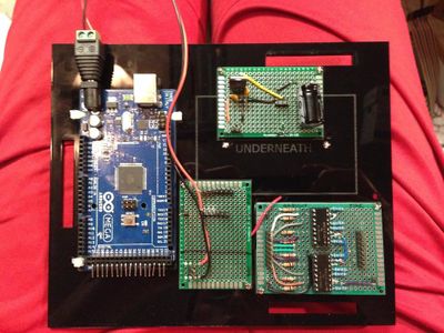


Install all of the buttons, switches and potentiometers into the panel surface. This is pretty self explanatory when you have the parts in hand.
Install all of the modules/boards onto the legs of the panel and the shelf. See the attached pictures for how my final setup went.
Solder all of the final connections from the buttons to the button sensing board and PWM board. If you are having trouble just revisit the Fritzing diagram and follow each wire trace. There are a lot of wires and it is easy to get things mixed up if you are not careful. Solder the common V+ and common GND connections where convenient for the potentiometer and key selector.
Run all wires to the digital I/Os on the Arduino where they belong. Try your best to follow the right wiring to where your code says they belong. As few mix ups will be fairly easy to diagnose later.
Install the keystone jacks into the keystone plate and make the connections to the header pins. Connect the display panel wires (red, black and green) to their corresponding positions on the voltage regulation board.
Slide the shelf over the feet, bolt the display panel to the lid and load some batteries. Flip on the power switch and start to diagnose any problems you may have. My overall installation we smoothly even though my wiring looks like a rats nest.
Check that all connections are secure and carefully lower the control panel into the case. You are almost all done! The wires should all be hidden and this thing should look very professional.
Step 21: Create Your Ignitors


There a a dozen or more Instructables on here on how to create your own ignitors for fireworks. Virtually all of them designed to be electronically activated with high current and Nichrome would work with my launcher.
I decided to build my own variant that was easy and quick to replace the nichrome when it broke, was inexpensive and easy to replace altogether and plugged in via the banana jacks/binding post solution.
I went with speaker wire to bridge the connection between the binding posts and the ignitor and made them each 10 feet long to give them some distance between fireworks if so desired. Attached to the end of the wire on one end is banana plugs that fit into the binding posts. Polarity does not matter in the least.
The ignitor end is essentially just a clothes pin with alligator clips screwed into it. The speaker wire feeds into the alligator clips where the screw down. The alligator clips hold the nichrome and bridge the electrical connection from speaker wire to nichrome. This makes replacing spent nichrome a 5 second exercise and is really handy if you are in the middle of putting on a show. The nichrome passes through the "teeth" of the clothes pin and is held against the fuse once inserted. The nichrome gets red hot, the fuse lights!
Some fuses I experimented with lit every time on the first time. Some were coated in a sort of enamel or wax that would keep them from lighting. The solution? Just stick a match head into the clothes pin with the fuse and it will light every time. I tried this modification with fuses on 10 different types of fireworks and they all lit flawlessly.
Step 22: Final Setup


Set up both boxes where you want them to go. Keep far enough away from the fireworks that you don't get yourself hurt.
Connect the control box with the firing box (ammo can) using three Cat 5 cables. I picked up 50 foot cables on Amazon for pretty cheap. I taped them together with white electrical tape to keep cable management easier and to make the line more visible so no one trips. Just be sure to connect the cables to the correct keystone port on both boxes. I labeled my cables and my posts to keep any confusion away.
Connect your ignitors. How ever many things you want to be able to blow up simultaneously, up to 8. Remember, the control box knows what is and is not connected and will automatically adapt. It will not try to launch what is not connected.
You are all done, insert your key and fire away! SAFELY and LEGALLY!
Please vote for me in the Summer Fun, Outdoor and Soldering Contests!
Be sure to check out all the YouTube videos I have posted. The one directly below would not embed into the Intstructable for some reason and it shows all 8 ignitors firing in sequence with a single button press!

First Prize in the
Summer Fun Contest

Runner Up in the
Soldering Challenge

Participated in the
Outside Contest


