

Introduction: Pier 9 Guide: Fusion 360 to OMAX Waterjet


Fusion 360 is not only a 3D-modeling program but also supports full CAM features, which will let you generate tool paths, run simulations and export files specific to certain CNC machines through Fusion 360's CAM environment.
This Instructable will show you how to setup tool paths from Fusion 360 using their CAM workspace.
Before you run this specific tool-pathing operation, you should project your 3D geometry onto 2D stock in Fusion 360 using this Instructable: Pier 9 Resource: Setting up 2D profiles for CNC in Fusion 360
Step 1: When to Use the OMAX Post

OMAX Make is the software used for controlling the OMAX Waterjet. There are two ways to create a tool-path file for OMAX Make. I'd recommend choosing the way that is both quick and less prone to error. Keep in mind that you'll likely be repeating the technique several times for the same cuts, as prototyping parts often doesn't work as expected the first time around.
One way is to use a 2D vector program to create your shapes, then generate tool-paths in OMAX Layout, and export an .ORD file for OMAX Make to do the actual etching and cutting. This works well for quick-and-dirty cuts, complex vector shapes and other situations where your source is in the 2D software. Working with 2D software is almost always faster than working with 3D software since there is one dimension less of calculations.
However, with this way there are at least 3 software packages involved and sometimes importing/exporting multiple file formats, which can create irregularities in your final output.
The second way is to use a 3D modeling program such as Fusion 360, where your part is 3D-modeled. From here, you export it using the CAM environment, which will generate the appropriate tool-path using the waterjet post-processor. Since a full-featured 3D program such as Fusion 360 is often slower to process geometry than a 2D vector program, it makes sense to use the F360->OMAX pathway only when you have parts that are from 3D models to begin with.
If there is just one piece to cut, it may be quicker to export that face as a DXF, since you can skip the process of projecting the 3D faces onto 2D stock.
However, when cutting or etching multiple parts on a single 3D model, I would strongly recommend using the F360->OMAX pathway.
Just one thing to note: the F360->OMAX post currently doesn't support 5-Axis machining, only profiles.
Step 2: Acquire Your Physical Stock


We'll want to figure out what kind of stock we will be using for the waterjet cuts. I recommend doing this before setting up the tool-paths, so that we can be more efficient in the software.
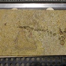
This particular stock is 1/8" aluminum that is 41" long and 17" wide. It's scratched up, but hey, it's just a sample.
Step 3: Setting Up 2D Profiles for CNC


Using the modeling environment in Fusion 360, we will set up 2D profiles on virtual stock.
This specific Instructable: Pier 9 Resource: Setting up 2D profiles for CNC in Fusion 360 will show you how to do this.
When we do this, make sure that our virtual stock is set to the same size as our physical stock.
I'm using a version of my Parametric Lantern 3D model, which looks more like a small skyscraper now.
The public link to view and download this model is here.
As you can see, when I set up the layout, I rotated the parts to optimize the cutting on the stock.
Also, I left a bit of room on the stock for the physical waterjet clamp itself on the left side.
Step 4: Make a Waterjet Setup in Your CAM Environment


From the Workspace menu, choose CAM to enter the CAM environment.
From the Setup menu, choose New Setup
In the Setup dialog box, under Operation Type, choose Water/laser/plasma
Choose the Stock tab, and for Mode, choose From Solid, which will make it so that your stock will be generated from a solid body (the Stock component).
Then, move the mouse over the solid object until it is highlighted and mouse-click on that object. The Stock Solid will now read "Body".
Press OK to dismiss the Setup dialog
Finally, just for the sake of clarity, I rename my setup as Waterjet in the Browser tree.
Step 5: Set the Work Coordinate System


After defining the setup, we want to match the work coordinate system to that of the waterjet machine. For most machines, the home position will be set to the lower-left corner of the stock.
Double-click on the newly-created water jet setup, which will bring up the Setup dialog.
Make sure you have Box Pointselected (this should be the default).
Now, zoom in on the lower-left corner of your stock and select that corner, the one at the front of the stock, which has the parts on the front.
Make sure the z-axis oriented correctly, so the positive direction (the direction of the arrow) is pointing up from your parts on the stock.
The axis indicator will now be at the lower-left of the stock. This will be the user home position of the waterjet machine.
Step 6: Setup Your Etch Contour


We will setup two contours: one for etching and one for cutting. We will want to etch the material and then cut it, so will setup the etch contour first.
Press the Waterjet Contour button at the top menu, which will bring up the Contour dialog box.
1. Define your contour settings
At the dialog box, make sure Type is Waterjet cutting(this should be the default).
The Cutting Mode should be set to Etch
The kerf width should be set to the kerf of your OMAX machine. For the one at Pier 9, it is .042 in.
Under Quality Control, select Machine uses quality
Keep the Contour dialog box open. Now, navigate so you can clearly see the etchable area — in this case the labyrinth extrusion.
Then click on the 2nd tab in the dialog box, which is the Geometry tab.
2. Select your contour
If you have a simple line or just a few lines, you can select just those lines and then press OK to dismiss the contour selection dialog box.
If simple selection does not capture all of a complex contour, you need to use a special series of steps:
(1) First, select any contour so that it is blue.
(2) Then click on that contour again, which will show a mini-toolbar
(3) Select another part of the contour, not directly next to this one.
(4) Then select the closed contour on the mini-toolbar. This will force it to search harder for a closed contour. The entire contour should now be selected.
(5) Press the [+] button the accept that contour. Now your entire contour will appear in blue. Press OK to approve this tool-path operation.
You should see a light blue line with an arrow on it, which will be the etch contour. I rename mine Etch for the sake of clarity.
Step 7: Setup Your Cut Contour


Like with the last step, press the Waterjet Contour button to begin a new contour.
At the contour dialog box, the Type should be Waterjet cutting(this will be the default)
For cutting mode, choose Through - low quality
For kerf, type in .042 in.
For quality control, like before, this should be Machine uses quality
Then click on the 2nd tab in the dialog box, which is the Geometry tab.
Now select each of the shapes you want to cut out. You do have to click on both the outside shapes and inside cuts. It does go pretty quickly.
Before generating the toolpath, you want to make sure you are cutting out the proper side of the shape — the interior rectangles, for example will not be material that we want to use, so we want to place the lead-in from the inside of the material.
Usually the Fusion 360 algorithms will suss out the proper way for your toolpaths to go, but if the red arrow is on the outside of the material, it means that the lead-in will occur on the outside of the rectangular cut, which will cause a gouge in the surface. To move the arrow towards the inside, just click on the red arrow and it will change to be on the inside of the material.
Press OK, which will generate your toolpath, and it will be indicated in yellow.
Rename the contour as Cut
Either of the two contours can be edited an any time, by simple double-clicking on them from the Browser
Step 8: Simulate the Toolpath


Select the Waterjet Setup, which includes both the Etch and the Cut contours on the Browser.
Then under the Action menu, choose Simulate. This will bring up a Simulate dialog box, which we don't need to worry about at this point.
Press the Start Simulate button — which looks like a play button on an old-style cassette recorder — and you can watch Fusion 360 show exactly how your path will be etched.
Because OMAX uses a quality setting for cut speed and not a specific feed rate, machining times will not be accurate. When you specify your material and its thickness in OMAX Make, the correct machining times will be calculated.
Press Closeto close the simulation dialog box when you are satisfied with the results.
Step 9: Run the Post-processor


With both contours still selected, choose Post-Process from the Action menu, which will bring up the Post Process dialog.
The fields in the dialog box are:
Source: Generic Posts
Post processor: omax.cps - Generic OMAX Waterjet
Program Numbers: this is just the default filename, which you can leave as is since you can change it more easily in the file save dialog box
Program comment: Parametric Lantern (or whatever the name of your document is)
Open NC file in editor: checked
The last option will open this in your default text editor, which will be Brackets or another program like this.
Press OK
You will be prompted to save the file and after doing so, your preview editor will launch.
Step 10: Preview Your Post-process


This is optional, but I find it helpful to do a quick scan of the file before going to the waterjet and loading it into OMAX Make.
The numbers look like a bunch of gobbledygook, unless you're a geek like me. The quality number is the important one.
If the quality = 0, then this is a traverse, quality = 6 is an etch, quality = 9 is a rough cut and quality = 2 is a heads-up traverse.
If everything looks good, bring your newly-created .OMX file to the waterjet machine and check it out in OMAX Make.
Step 11: Prepare for Cutting


First, load the .omx file in OMAX Make. It should feature the toolpaths that you just created.
Clamp your material to the bed of the waterjet. Set your user home so that it is close to the lower-left edge of the material, set your Z-axis height, pressurize the garnet and turn on the pumps, use Spot on Path to make sure there are no collisions.
(By the way, this photo is from the opposite side of the waterjet, to get better lighting, where the machine home is on the upper-right).
Step 12: Cut Your Material


The cuts and etching for this material took about 22 minutes. By default, after each cut, there is a heads-up traverse to the next, which is a bit slower but also safer for avoiding a head collisions with any sort of flipped up piece of metal.
I was quite happy with the way this turned out.
Step 13: Done!

And in the end, the physical model resembled the actual model. Victory!
I hope this Instructable was helpful.


