

Introduction: Getting Started With MicroPython on the ESP8266


Do you want a different way to program the ESP8266-based boards rather than the common method using Arduino IDE along with C/C++ programing language ?
In this tutorial we will learn who to configure and control an ESP8266 board using MicroPython.
BUILD TIME: 60 MINUTES
DIFFICULTY: RATING: Easy
Step 1: What Is MicroPython ?
MicorPython is one of the many programming language that can we use to program the ESP8266 module. It is a lean and fast version of the Python 3 programming language and has several advantages over traditional programming languages such as C and C++.
MicroPython is designed to be compatible with normal Python as much as possible. It has a complete Python compiler and runtime, and provides an interactive prompt known as REPL (Read-Eval-Print Loop).
MicorPython is designed to support few different types of microcontrollers. But for this tutorial I'm going to work with just one model: the ESP8266-based board (NodeMCU). Note that there are a few different boards that you can buy with the same chip.
Reading & Resources:
Step 2: Requirements


To be able to follow this tutorial you just need to have basic coding experience with Python.You do not need to have any previous knowledge of microcontrollers, electronics, or even MicroPython.
You will also need a Windows, Mac or Linux computer with a free USB port, as you will connect a microcontroller to your computer to program it.
Parts Required:
1 x NodeMCU ( or other ESP8266 based-board)
1 x Red 5mm LED
1 x Breadboard
Jumper Wires.
Step 3: Why ESP8266 Based-board ?

One way you can get the most out of your ESP8266 is by using MicroPython. Also, the ESP8266 module is one of the best platforms on which to learn how to use MicroPython. This is because the ESP8266 provides simple GPIO pin control functions as well as wireless functionality, allowing you to test all aspects of the MicroPython programming language.
The ESP8266 chip is popular in the open source development industry. There are many development boards from different manufacturers that use the ESP8266 chip. MicroPython has been designed to provide a generic port that can run on most of those boards, with as few limitations as possible. The port is based on the Adafruit Feather HUZZAH board When using other ESP8266 boards, make sure you check their schematics and datasheets so that you can identify the differences between them and the Adafruit Feather HUZZAH board. That way, you can accommodate the differences in your code.
Reading & Resources:
Step 4: Setting Up Your Computer


There are several things you have to set up before using MicroPython to program your ESP8266 board.
We will be going through the setup process in this step. This way you will you know how to configure the ESP8266 board to be used with MicroPython.
Getting ready
All you need from this step to step 6 is your ESP8266 and a USB cable. Connect your ESP8266 board to your computer.
How to do it...
STEP1: Install device drivers
If you have a Linux computer, then you do not need to install any device drivers for the drivers for the microcontroller to be recognized.But it you have a Mac or a Windows machine, a driver is needed to allow the computer to recognized the microcontroller as a serial device.
https://www.silabs.com/products/development-tools/software/usb-to-uart-bridge-vcp-drivers.
STEP2: Install Python
The tools that you are going to use to communicate with the ESP8266 are written in Python, so you need to install Python on your computer.
If your operating system does not provide a pre-packaged Python, you can go to https://python.org to download an official build for any of the supported operating systems.
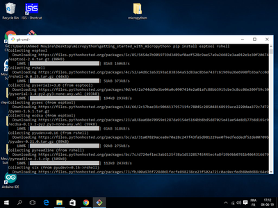
STEP3: Install esptool and rshell
Install two packages that are going to help you manage your board using pip.To do this open your terminal and run
pip install esptool rshell
STEP4: Download MicroPython
Download the latest MicroPython firmware .bin from the following link: https://micropython.org/download#esp8266
At the time I'm writing this, the current version is 1.11, and the firmware file is called esp8266-20190529-v1.11.bin
By the time you do this you may find a newer release.
Attachments

Step 5: Flashing MicroPython With Esptool.py


Before flashing a new firmware into the board it is a good idea to erase any previous data.This is something that you should always do so that the new firmware runs from a clean state.
Go where you have placed the .bin file. Use esptool.py to erase the flash.
For Linux:
esptool.py --port /dev/ttyUSB0 erase_flash
For Windows:
esptool.py --port COM3 erase_flash
You may have to change the serial port in your command to the serial port that your ESP8266 board is connected to. If you do not know the serial port number of your ESP8266, you can check in the Arduino IDE. Just open the IDE and then click on Tools | Ports. You should see the serial port of your ESP8266 board listed there. Replace the serial port in the command (/dev/ttyUSB0 ) with the serial port of your board.
Now that the board is completely erased, you can flash the MicroPython build that you just downloaded.This is also done with the esptool.py command:
esptool.py --port /dev/ttyUSB0 --baud 460800 write_flash 0 esp8266-20190529-v1.11.bin
This command is going to write the contents of the MicroPython .bin file to the board at address 0.
Make sure you change the name of the firmware .bin file in the command ( esp82688-2019-080529-v1.11.bin) to that of the firmware you downloaded.
Once the firmware is successfully installed on your ESP8266 board, you can access REPL on your board via a wired connection ( UART serial port) or thought WiFi.
Step 6: Using the MicroPython REPL With Rshell

You are now ready to start MicroPython on your ESP8266 board.
What I'm going to show you how to connect to the Python prompt running on your board.This is called the REPL, which stands for "Read-Eval-Print-Loop". This is the standard Python prompt that you are probably used to see when working with the regular Python interpreter, but this time it is going to be running on your board, and to interact with it you are going to use the serial connection to your computer. Ready?
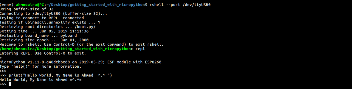
To connect to your board and open a REPL session, enter the following command:
rshell --port <your board port name>
This command will bring you into the rshell prompt. See photo above.
If you are following this tutorial on Windows, note that rshell has a history of problems when running on Windows.
So in order to fix that type:
rshell -a --port COM3
From this prompt you can perform management tasks related to your
microcontroller board, and also start a Python REPL that you can use to interact with the board in real time.So just entering the following command:
repl
To make sure everything is working, type a simple Python sentence:
print("Hello World")Step 7: Controlling Pins Using MicroPython


In this step, we will learn how to control the ESP8266 pins with MicroPython. To do that we will come up with a setup where we will be switching the state of the an LED connected to an ESP8266 board GPIO pin. This will help you understand how to control digital outputs using MicoPython.
Getting ready
You will need the following things to accomplish this STEP:
1 x NodeMCU
1 x Red 5mm LED
1 x 220 Ω Resistor
1 x Breadboard
Jumper Wires
The Build
Begin by mounting the LED onto the breadboard. Connect one end of the 220 Ω resistor to the positive leg of the LED ( the positive leg of an LED is usually the taller one of the two legs). Connect the other end of the resistor to pin D1 of the ESP8266 board. Then connect the negative leg of the LED to the GND pin of the ESP8266 board. The connection is as shown in the above diagram.
Once the setup is complete, connect the ESP8266 board to your computer via a USB cable.
How to do it...
Type the following code in your REPL:
# blink LED every 1 second
def blink(pin=5, time=1)  # blink function by default pin=5, time=1s
    import machine 	  # the machine module holds the pin configurations and modes
    from time import sleep  			# import sleep for some delay
    LED = machine.Pin(led_pin, machine.PIN.OUT)	# configure LED as OUTPUT
    while True:					# run forever
        LED.value(1)				# set LED to HIGH
        sleep(time)				# wait 1 second by default
        LED.value(0)				# set LED to LOW
        sleep(time)				# wait 1 second by default
Type blink() in your RPEL session to test this code.This will blink the LED connected to the GPIO5 each 1 second.
You could change the pin and/or the time by calling:
blink(pin=<pin_number>, time=<time_value>)
Press ctrl+c to exit the running code.
You can use MicroPython to read an input from connected to the ESP8266. Proceed to the next step to learn how to do that.
Check the video if you stuck.
Step 8: Fading the LED


In this step, we will learn how to adjust the brightness of the LED using a rotary potentiometer. We will use a technique called Pulse Width Modulation (PWM), it allows us to dim the LED with up to 256 settings.
Notice: All the pins of ESP8266 can be used as a PWM pin except GPIO16 (D0).
Getting ready:
You will need the following things to accomplish this STEP:
1 x NodeMCU
1 x Red 5mm LED
1 x 50 KΩ Rotary Potentiometer.
1 x Breadboard
Jumper Wires
The Build
The connection is as shown in the above diagram: Once the setup is complete, connect the ESP8266 board to your computer via a USB cable.
How to do it...
Type the following code in your REPL:
# Fading LED every 0.5 by reading data from the Potentiometer
import machine
from time import sleep
led_pin = 5     		     # led pin
POT = machine.ADC(0)	             # ADC0 pin
LED = machine.Pin(led_pin)	     # create LED object
LED_pwm = machine.PWM(LED, freq=500) # create LED_pwm object and set frequency to 500Hz
while True:
    LED_pwm.duty(POT.read())      # get the value from the Pot and set it to the duty cycle
    sleep(0.5)			  # wait 0.5
This will change the brightness of the LED connected to GPIO 5 by changing the value of the potentiometer.
Press ctrl+c to exit the running code.
Check the video if you stuck.
Step 9: Where to From Here ?
So far we have seen how to configure and run MicroPython on ESP8266-based boards. we learnt how to control pins to blink a LED then we added a potentiometer in order to control the brightness of the LED using pulse width modulation technique.
Now we can read data from sensor and send it to the cloud, we can also create a HTTP server where you could print our data in a simple webpage,etc ...
This give us many idea of Internet of things (IoT).
Step 10: Conclusion
There you have it! Go forth and conquer the world of MicroPython.
if you have any question of course you can leave a comment.
To see more about my works please visit my YouTube channel:
Thanks for reading this instructable ^^ and have a nice day.
See ya.
Ahmed Nouira.

![Tim's Mechanical Spider Leg [LU9685-20CU]](https://content.instructables.com/FFB/5R4I/LVKZ6G6R/FFB5R4ILVKZ6G6R.png?auto=webp&crop=1.2%3A1&frame=1&width=306)


