

Introduction: Giant Clicker Pen!


The goal was to build a mechanism big enough to teach and be handled by fourth-graders.
Collaborators: Ryan Anderson, Scott Taysom, Steve White, Brettany Rupert, Clifton Dudley, Wyatt Felt
Here's a look at the materials we used:
Giant Spring (taken from a broken fan base)
clear tube: 30"
plexiglass: .25" or .375" thick, 5" long .5" (2 of them) wide
plexiglass: whatever thick and abt 2.75" dia
1" PVC pipe abt 3'
upper pusher - 2.25" diameter plastic 8" long
lower pusher - 2.25" diameter plastic: 7.5" long
tip - 2.75"+dia 4.5"long
spacer - 2 1/4" by 1.5" long
set screws - various sizes
Big ol' Marker
Small spring and guide rod for cams
~$60, weighs in at 4 lbs
Step 1: How It Works


The mechanism for a clicking pen is a bi-stable cam system. It is actuated by a guide pin and a compression spring In the retracted position the spring is pre-loaded in order to keep the upper and lower cam pressed together.
When the pen is pressed to the change point, the lower cam clears the guide pin (Fig. 1b). The force of the compressed spring is larger than the friction on the inclined surfaces of the cams, and the lower cam rotates as it retracts into the extended position (Fig. 1c).
By compressing the spring past the change point again, the lower cam rotates and the upper cam is guided back into the retracted position (Fig. 1d). The stroke length from the retracted to extended position is 1”.
Step 2: Obtain Spring and Scale CAD Files


We scaled our entire project around a spring we'd recovered from a fan base.
Our CAD files are designed to work with a spring that is slightly larger than 1" and about 14" long uncompressed.
We've attached the files we used below. They will probably need to scaled to work with whatever spring you have available.
Attachments

Step 3: Build It!


The central rod is a 1" PVC pipe.
The CAM mechanisms were cut using a 3-axis CNC Mill.
The Axially-symmetric parts were turned on a lathe.
The guiding sliders (trapezoidal) were cut on a laser-cutter.
We used set screws to hold the nested parts in place
We used a Dry-erase marker as our pen tip.
Challenges/Refinements
As most engineering projects, when we began to build our physical model we encountered challenges that the CAD model had not predicted. One of the biggest challenges that we encountered was friction between the two cams. We anticipated this friction and to prevent it from binding the mechanism, we inclined the sliding surfaces of the cam to 45° in the CAD model (Fig. 4).
When we built the model we found an unanticipated problem during the retraction of the mechanism where the upper cam became wedged between the flat face of the lower cam and the slider. Instead of the pen automatically popping back up and letting the lower cam fall into its extended stable position, the user needs to fiddle with it to overcome the friction.
The pen tip prevented the mechanism from running smoothly. Due to manufacturing errors the two guiding circles on the pen tip were not concentric. In order to solve this problem we decided to widen the radius of the cylindrical hole in the pen tip. This gave the pen looser tolerances and allowed the pen to extend and retract easier.
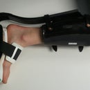
Another problem that we encountered was the effect the planned gaps between the pen wall and the cams had on the hardware. The outer diameters of the cams were turned down so that there would not be friction between the cams and the wall as they slid up and down. However, this spacing made it difficult for the cams to remain concentric during mechanism motion. In order to solve this problem we added a guiding rod (see picture) between the two cams to maintain their concentricity.
We also had some issues with material fracture. We originally designed the pen end-cover using .25” acrylic, which we cut with the laser cutter. However, the recoil of the cam returning from the change point back to the retracted stable position caused the acrylic to crack. In order to solve this problem we replaced the acrylic cover with a thicker piece of less-brittle plastic.

Participated in the
Make It Real Challenge


