

Introduction: Graphite-Controlled Mono Synth


Here’s a cool little mono-synth you can make cheaply with a 7555 that uses the graphite from pencils as a variable resistor.
Step 1: Parts List
Parts You’ll Need:
-Solderless breadboard
-22 awg solid core wire
-7555 Timer
-2 1kΩ resistors
-1µF capacitor
-9V battery
-battery clip
-9V to 5V voltage regulator
-graphite pencil and paper
-electrical tape
-audio cable and speakers or headphones
If you're new to electronics or working with breadboards, check these out:
ICs, 555: https://www.instructables.com/id/Know-Your-IC-555-Timers/
Breadboards video: https://www.instructables.com/id/Breadboard-Basics/
Breadboards how-to: http://www.techdose.com/electronics/How-to-Use-Solderless-Breadboards/252/page1.html
Step 2: BUILDING THE CIRCUIT


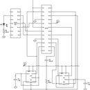
Using the 7555, build this circuit on your breadboard^ (ignore everything right of the LED)
This IC is an astable oscillator, which means it produces square waves. At high enough frequencies (anywhere above 20Hz), those waves can be turned into audio!
Step 3: BUILDING AND CONNECTING THE GRAPHITE MIXER

Take your pencil and rub the graphite onto the paper making a thick, long rectangle. We want the graphite to conduct electricity, so make sure there are no lapses. This is your mixer. Secure a wire (white) to one end of your rectangle. You may need to tape down the wires so they don’t move. Connect the free end of that wire to ground on your breadboard. Take another wire (green) and connect pin 3 of your 7555 to the tip of the audio/headphone jack. Then, connect the sleeve of the jack to ground on your breadboard (via black wire).
You can connect the final wire (red) to either of two pins for different results. If you connect the wire to pin 5, the circuit will always play a constant tone. If you connect the wire to pin 7, the circuit only plays a tone when the free end of the wire is in contact with the graphite. The pin 7 option is usually more practical, unless you want a pedal tone on your synth.
Step 4: POWERING YOUR CIRCUIT/MAKING SOUND


Make sure the ground rails are connected for common ground, and the voltage rails for common voltage. Connect the voltage regulator to the voltage rail at pin 3 (output) and ground rail at pin 2 (ground). The voltage regulator converts 9V into 5V, which we need to power the circuit. To power up your circuit, connect a 9V battery to the input at pin 1. Although it is not necessary, you should use an LED as an indicator for when the circuit is properly powered.
To get sound, make sure your mixer is connected to a speaker through the audio jack. If you don’t have this, headphones work just fine. You will have to press down on the exposed wire (the red one) so that the exposed tip connects with the graphite. The graphite acts as a variable resistor. As you change the distance between the ground wire and your red control wire, you change the resistance on that pin (5 or 7), which changes the pitch of the sound!


