

Introduction: HD44780 LCD to I2C Adapter Board for the Bus Pirate


Cheap character LCDs based on the HD44780 chipset come in a variety of sizes: 2x16, 4x20, etc. These displays have two standard interface modes, 4bit and 8bit parallel. 8bit requires a total of 11 data lines, 4bit requires 7 (6 for write-only). Some LCDs support an additional serial data mode, like the VFD I covered at Hack a Day.
HD44780 LCDs are generally 5volt parts with a separate supply for the back light. The Bus Pirate only has five 5volt tolerant I/O pins, so we made a small adapter board with enough pins to control the LCD. The Bus Pirate controls the adapter board through its LCD interface library.
Continue reading about the Bus Pirate HD44780 character LCD adapter board and interface library.
I can have PCBs, kits, or assembled kits produced by Seeed Studio for about $15, including worldwide shipping, more here.
I couldn't include some formatting elements and HTML tables in an Instructable, you can see the original post at the Dangerous Prototypes blog.
Step 1: Hardware


Overview
In this article we outline an I2C adapter board for HD44780-based LCDs. We demonstrate it with a Bus Pirate universal serial interface. The Bus Pirate source code for the I2C-based HD44780 interface library is public domain, so it's free to adapt to your own projects.
Hardware
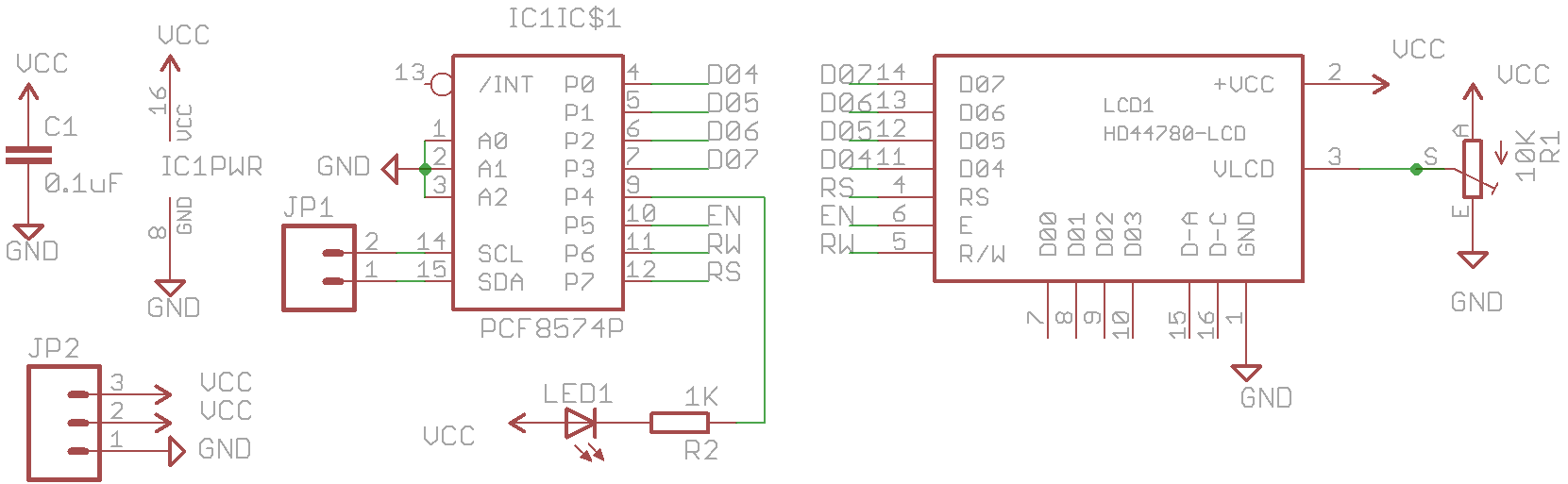
Full size circuit image [PNG]. The circuit and PCB were designed with the free version of Cadsoft Eagle. The design files can be downloaded from the Bus Pirate SVN. Before using the adapter board, be sure to verify the datasheet for your LCD against the adapter pinout. Not all LCDs are the same.
PCF8574 I/O expander IC
This is a simple 8 I/O expander chip that's controlled through the two-wire I2C interface. The I2C interface is accessible from header JP1.
The PCF8574 works from 2.5 to 5volts. The I/O pins operate at the supply voltage, so if we feed it 5volts it interfaces the LCD at 5volts. C1 (0.1uF) decouples the IC from fluctuations in the power supply.
One pin of the PCF8574 controls a 3mm LED (LED1) through current limiting resistor R2 (1000 ohms). The LED lights to indicate successful communication between the Bus Pirate and the adapter. The PCF8574 can't source enough current to power the LED, so we power the LED from the 5volt supply and switch the ground.
LCD
The adapter board communicates with an HD44780-based character LCD in 4bit parallel interface mode. The 4bit interface pins - RS, RW, EN, and D4-D7 - are connected to seven of the PCF8574 I/O pins. We like to use 0.1" male pin header to connect the adapter to an LCD, you can usually lean the LCD against the pins to create sufficient contact for a quick test.
Trimmer resistor R1 (10K) provides a contrast adjustment voltage to pin 3 of the LCD header.
We didn't connect the backlight pins because there's so many different backlight styles. Providing power for an LED backlight might damage a screen that requires a negative voltage supply.
Power supply
Most LCDs require 5volts, provide an external power supply through header JP2. We provided a second power supply pin to connect the Bus Pirate's pull-up resistors.
PCB
The circuit and PCB were designed with the free version of Cadsoft Eagle. The design files can be downloaded from the Bus Pirate SVN. The PCB is a single-sided, all through-hole design with a single jumper wire (shown in red).
We can have PCBs, kits, or assembled kits produced by Seeed Studio for about $15, including worldwide shipping, more here.
Partlist
Part
Value (all through-hole)
C1
0.1uF/10volts+
R1
10000 (10K) ohm single turn trimmer/potentiometer, 6mm
R2
1000 (1K) ohm resistor, 1/4 watt
LED1
3mm (T1) LED, red
JP1+JP2
0.1" male header, 5 pins
IC1
PCF8574N, 8bit I2C I/O expander DIP16
ICS1
16 pin DIP socket for IC1
I couldn't include some formatting elements and HTML tables in an Instructable, you can see the original post at the Dangerous Prototypes blog.
Step 2: Connections

Device: HD44780 character LCD.
Bus: 4bit parallel, with PCF8574 I2C adapter board.
Power requirements: 5volts.
References:example datasheet [PDF], HD44780 command reference, HD44780 LCD uber-site.
Complete Bus Pirate session log for this demonstration.
We designed the adapter for the LCD library of the Bus Pirate universal serial interface, but it'll work with anything that can speak the I2C protocol. Take a look at the Bus Pirate source code for an example I2C->HD44780 implementation.
Connect the Bus Pirate to the adapter board as shown in the table. The table also shows the raw connections to the PCF8574 IC if you're following along without an adapter board.
Connect the adapter to a power supply sufficient for the LCD, generally 5volts. The I2C connection between the adapter and the Bus Pirate requires pull-up resistors between 2 and 10K. Here's more information about mixed voltage interfacing with pull-ups, and the Bus Pirate on-board pull-up resistors.
I couldn't include some formatting elements and HTML tables in an Instructable, you can see the original post at the Dangerous Prototypes blog.
Step 3: Step 1. Setup Library
Interfacing
We've covered the adapter design and how to connect it to the Bus Pirate, now it's finally time to write something to the LCD.
HiZ>m <<<set mode menu
1. HiZ
...
11. LCD
12. HWI2C
(1) >11 <<<LCD interface mode
MODE SET
LCD type:
1. HD44780 (using PCF8574 IO expander)
(1) >1 <<<currently only supports HD44780 LCDs
HD44780 LCD TESTER
REQUIRES PCF8574 I2C IO EXPANDER
LCD>W <<<big 'W' turns on the power supplies
POWER SUPPLIES ON
LCD>p <<<configure the pull-up resistors
1. Pullup off
2. Pullup on
(1) >2 <<<turn the pull-ups on
PULLUP RESISTORS ON
LCD>v <<<get voltage report
VOLTAGE MONITOR: 5V: 4.9 | 3.3V: 3.3 | VPULLUP: 5.0 <<<check Vpu
LCD>
Press 'm' in the Bus Pirate terminal and choose the LCD library. It currently it only supports HD44780 character LCDs using the PFC8574 adapter described in the first half of this article (option 1).
Enable the power supplies (big 'W') and pull-up resistors (menu 'p'). Check the voltage monitor (menu 'v') and make sure that the pull-up voltage (Vpullup) reads around 5volts.
Step 4: Step 2. Reset and Initialization


This table outlines the single-byte commands that control an HD44780 LCD, here's a detailed reference. These commands can be entered from the Bus Pirate command line, but we've made macros for most of them to save time.
LCD>(0) <<<show macro menu
0.Macro menu <<<this menu
1.LCD Reset <<<reset the LCD
2.Init LCD <<<reset and initialize the LCD
3.Clear LCD <<<clear LCD, return cursor to 0
4.Cursor position ex:(4:0) <<<set cursor postion
5.Write test text <<<will be removed by firmware v2.1
6.Write :number test numbers ex:(6:80)
7.Write :number test characters ex:(7:80)
8.Insert text at cursor
LCD>
Macro 0 displays the macro menu for any Bus Pirate mode.
LCD>(2) <<<initialize LCD macro
Display lines:
1. 1 <<<single line display
2. Multiple <<<multiple line display
(2) >2 '
RESET <<<macro 2 includes a reset sequence
INIT <<<initialize the LCD
LCD>
The initialize LCD macro (2) configures the screen for 4bit interface mode, enables cursor display, and sets a few other helpful options. Configure the number of display lines, choose 1 for a single line display, or 2 for all other displays.
After initialization, the screen should be clear with a cursor visible in the corner. If it didn't work, check the I2C connection, pull-up resistors, and power supply, then try again.
HD44780 LCDs need to be reset with a special signal sequence before they can be initialized for 4bit or 8bit interface mode. Macro 1 creates this sequence. Macro 2 includes the reset sequence, so there's no need to use macro 1 before macro 2.
Step 5: Step 3. Write Test Characters


LCD>(6:80) <<<write 80 numbers
LCD>
The write numbers macro fills the LCD with test numbers between 0 and 9. The number after the colon tells the Bus Pirate how many test numbers to write, we're using a 4x20LCD, so we write 80 numbers to fill it. Notice that the cursor ends at position 0, under the first '0'.
LCD>(7:80) <<<write 80 characters
LCD>
The write characters macro fills the LCD with ASCII characters, enter the quantity after the colon. Notice that the fist line continues on the third, the third on the second, and the second on the last. The characters aren't continuous because character LCDs don't wrap from one line to the next. We'll talk a little more about this later.
Step 6: Step 4. Clear LCD
LCD>(3) <<<clear the LCD
CLEARED
LCD>
The clear LCD macro sends the HD44780 command that erases the screen and returns the cursor to the first position.
You could also do any of these operations without the macros, refer to the command table at the beginning of this section. Enter '[0b1' in the Bus Pirate to set the interface to command mode ([) and send the HD44780 clear screen command (0b00000001) without a macro.]
Step 7: Step 5. Type Text


LCD>(8) <<<insert user text
Enter text to insert at the cursor position.
HD44780 LCD demo <<<we typed this
LCD>
After clearing the LCD in step 4, the cursor is positioned at the first block. We could also set it with the macro (4:0), which moves the cursor to the first character.
The insert text at cursor macro asks for text input, and then copies it to the LCD when you press enter.
LCD>(4:0x40) <<<position the cursor at 0x40
LCD>(8) <<<insert text
Enter text to insert at the cursor position.
Bus Pirate v2go <<<we typed this
LCD>
Writing to the second line is a little more complicated, it actually starts at character 64 on a 4x20 LCD. If you continue writing from the end of line 1 (character 20) then you'll end up at the beginning of line three! This page has a nice collection of memory maps for most character LCD sizes.
First, we position the cursor on the second line (4:0x40). Next, the 'insert text' macro grabs our input and copies it to the LCD.
LCD>(4:0x14)(8)(4:0x54)(8) <<<multiple macro syntax
Enter text to insert at the cursor position.
Firmware v2.0+ <<<we typed this
Enter text to insert at the cursor position.
DangerousPrototypes <<<we typed this
LCD>
The Bus Pirate accepts multiple macros on the same line, so the entire screen can be written at once. We wrote to the last two lines with a single line of syntax.
We could use '(3)(4:0)(8)(4:0x40)(8)(4:0x14)(8)(4:0x54)(8)' to clear the LCD and write all four lines with a single syntax entry.
Step 8: Step 6. Reading From the LCD
The Bus Pirate and LCD adapter board can read from the LCD. We'll read the text we wrote to the screen (DDRAM), but you can also read settings and custom character ram (CGRAM) by setting the correct address.
LCD>[0b10000000 '''<<<set the read pointer''']
HD44780 RS LOW, COMMAND MODE <<<register select pin low
CMD WRITE: 0x80 <<<wrote to LCD as command
LCD>
First, we tell the Bus Pirate to send data to the LCD command register ([). Next, we use the set DDRAM address command (0b1xxxxxxx) to set the read pointer to the beginning of the DDRAM (xxxxxxx=0000000).]
LCD>]rrrrrrr <<<read data memory
HD44780 RS HIGH, DATA MODE <<<register select pin high
READ: 0x48 <<< 'H'
READ: 0x44 <<< 'D'
READ: 0x34 <<< '4'
READ: 0x34 <<< '4'
READ: 0x37 <<< '7'
READ: 0x38 <<< '8'
READ: 0x30 <<< '0'
LCD>
Finally, tell the Bus Pirate to read from data memory (]), and then read a few bytes (rrrrrrr). We got "HD44780", the text we wrote to the screen in step 5.
You should also be able to use the shortcut r:7 to read seven bytes, but it's not working in the current firmware - we'll fix this prior to the next release.
Step 9: Doing More
Give a general description of the StepThe HD44780 character LCD adapter is a handy accessory for the Bus Pirate. It can be used for a quick test, or more advanced logic development.
In addition to LCDs, the eight 2.5volt-5volt I/O pins might be useful for other high pin-count Bus Pirate applications.
We can have PCBs, kits, or assembled kits produced by Seeed Studio for about $15, including worldwide shipping, more here.
I couldn't include some formatting elements and HTML tables in an Instructable, you can see the original post at the Dangerous Prototypes blog.


