

Introduction: High Speed Sensitive Drill Press


A regular drill press spins too slowly for very small drill bits and parasitic forces reduce the "feel" for what the drill bit is doing. Both of these factors often contribute in a major way to broken small drills. A sensitive drill press is ideal for drilling PCBs with sub mm diameter drill bits.
For some time I have been thinking about making a sensitive high speed drill press using the high speed spindle that I use only occasionally on my mill and also lathe. Then a drill press meant for pistol drills came up on a local classified for sale list. It was of higher quality than most items of that genre that I have seen, and I bought it for only 20 euros.
I have made a 20 minute video which explains the conversion as well as demonstrating the requirements of a sensitive drill and showing some tests of how I checked the success of my efforts. Video link This video is an essential part to aid the understanding of this Instructable.
Supplies
- High speed spindle and VFD if required. There are tons on the internet.
- Drill press adapter for pistol drills.
- Lead. I bought from a scrap metal yard.
- Steel pot for the lead, or some tube to make one. Could use an empty food can, but not an aluminium drink can.
- 2 pulleys or small wheels. Could convert skate wheels.
- Thin steel cable. Often sold in hardware stores for picture hanging.
- Angle iron if you need a frame to raise it up..
Tools
These will depend on the degree of compatibility between the spindle and the drill press adapter that you find.
- I used a lathe and milling machine but it could have been done without them.
- Mig welder. Any type of welder would do fine.
- Drill.
- Miscellaneous hand tools like hacksaw, files, paint brush etc.
- Blow torch.
Step 1: What Is a Sensitive Drill?

Briefly a sensitive drill is one in which most, preferably all, of the operator applied force is directly related to the in-line force needed to push on the drill bit.
You might ask "Don't all drill presses do that?". Well no they don't. It is normal to have strong return springs on the quill which may completely overwhelm the downward drilling force and so the operator cannot feel what is happening. In addition the spring return force varies with quill position getting stronger as the hole gets deeper.
The ideal is for the quill or spindle weight to be balanced exactly in a mechanism with the minimum friction.
The video here shows how I do this in great detail. Video link
Step 2: Gather Your Parts.


Before deciding how you are going to make yours, you will need to get the two main pieces.
Firstly, I suggest that you decide on your spindle. For me that was a "no-brainer" I had a 3 phase 400 Hz high speed spindle that I occasionally use in my milling machine for small cutters. I figured that it would get used more as the power source in a high speed drill. It could be transferred to the mill or lathe when required.
These spindles are available in different power ratings from 1 kW upwards and either air or water cooled. For this project I think that air cooled is fine because the loading from drilling small holes will be minimal, if you also want to use it in a router or for similar high intensity work as well then go for water cooled and a higher powered spindle.
There are alternative power sources such as electric routers and multi tools like the Dremel type. Just make sure that it has a chuck or collets capable of holding the smallest drill bits that you plan on using. My spindle uses ER11 collets which go down to 0.5 mm diameter and up to 6 mm. A regular drill press is better for any larger bits.
Once you have the spindle you can then look around for a drill press adapter that best suits it. Some such adapters have a lot of slop in the mechanism but these are too be avoided if you plan on using very small drill bits. Look for the most solid and well designed device that you can find, preferably with a rack and pinion drive rather than a cheapo lever system.
Step 3: Make Them Fit


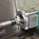
I was lucky enough to find a nice quality drill press adapter on a local classified adverts site, Craig's list in the US would be a good place to look if you are in the US.
The clamping hole for holding the drill was 3 mm smaller than the nose diameter of the spindle. Taking into account the amount of metal on the spindle and the adapter I machined 1 mm diameter off the spindle nose and 2 mm off the adapter to get a perfect fit.
The spindle was machined in my lathe and the adapter was bored out in a milling machine.
Step 4: Counter Balancing


The mounting slide and the spindle motor weigh a total of 4.23 kgf. Without any form of counter balancing this will apply 4.23 kgf. to the drill bit without additional operator force. I have already shown the problem with using springs to balance out this weight. However, a counter weight of equal value can balance it out exactly save for any friction.
The second and third photos above show how I used a counter weight connected via a steel cable over two pulleys. This results in an extremely sensitive movement of the spindle assembly.
Step 5: Making the Counter Weight


In the previous step I showed that we needed a counterweight of 4.23 kg. I calculated the volume needed and cut off a short length of steel tubing with a bit more than that volume. A plate welded to the bottom side sealed it off. I bought some old lead plumbing from a scrap metal merchant and melted it into the pot with a blow torch.
If you do not want to mess with melting lead you could use it in whatever form you get it, but your pot will need to be larger if it is not melted.
I used square tubing for the pot because it is what I had. I would use round given a choice.
Step 6: Raise Me Up.


I do not like bending my ancient back too much when working and I like most of my tools to be higher than average. That was the case with this drill project. I made a frame to raise it up to a more comfortable level and the design of the frame was determined by a desire to fit some plastic drawers for keeping collets and associated parts.
The frame was welded up from pieces of angle iron from my scrap box.
Step 7: Finishing Touch


As it came the base had large T slots. Most work that I will do with the sensitive drill will be hand held and so the T slots are not needed and cam made it difficult when drilling small pieces which might be smaller than the T slots. To avoid such a problem I added a a 6 mm aluminium plate over the base and drilled a single clearance hole in the centre.
That's it folks. I have a very nice drill press suitable for small drills with a very sensitive feel to it. I cannot guarantee that I will never break a small bit but the chances are greatly reduced compared to using a regular drill press. The high speed also helps to put the cutting speeds more inline with the needs of small bits.
I do recommend that you watch the video linked to in the introduction. This shows how the counter balancing works in much greater detail and some extra things to consider.
Tony Foale June 2019
You can visit my web site at Tony's web site
My Youtube channel has several more examples of tools and test equipment that I have made and can be found here Tony's Youtube please like, share and subscribe to my channel if you find the content of interest.


