

Introduction: Home Automation Using BLYNK App


In this project,I have shown that how anyone can control his/her home appliances remotely using his/her mobile phone. For this an application must be installed in your mobile.the name of this application is BLYNK App ( Download link is given in description) and an uninterrupted internet service is recommended. I have controlled only a 15W bulb ,but you can control any home appliances ( tube light ,fan etc.).
Step 1: EQUIPMENTS REQUIRED

1. Arduino UNO.
2. Relay module(A.C. - 230 V, D.C.- 5 V, in pic).
3. Bulb(15 W,230 V or any other wattage)
4. BLYNK App( installed in your mobile, link given below).
5. 230 V power supply. (A.C.)
6. Jumpers.
7. 12 V power supply .(D.C.)
8. Bulb holder and wires.
▪ Link (BLYNK App) :-
Step 2: CIRCUIT DIAGRAM


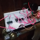
Connection is very simple .In the pic it is given that the relay module is powered by 5 V ,but in my model I have powered the relay module using 12 V adapter.Generally it is better to power with 12 V. There are 6 pins in relay module.
Pin 1 - 12 V/5 V
Pin 2 - GND
Pin 3 - Signal
Pin 4 - COM (Common)
Pin 5 - NO (Normally open)
Pin 6 - NC (Normally connected)
Pin 1 is used for powering the module. Basically relay module acts as a switch to control A.C. appliances. So the Pin 3 is used to send the signal whether we want to on/off the appliances.Pin 3 is connected to any one of the digital pins of Arduino UNO . In my project it is PIN 13 of Arduino UNO. As per the diagram the neutral line will be connected to the bulb directly , but the live line will be connected to the bulb via the module.The live line coming from the plug(230 V a.c.) will be connected to COM (Pin 4) and the wire from the other pole of the bulb will be connected to NO (Pin 5). As I have not used any Ethernet shield so the Arduino must be connected to your laptop ,so that it can receive the signals through laptop(connected to internet).You can also use NODE-MCU ,in that case you don't require the laptop for receiving signals as NODE-MCU can receive signals via internet.
Step 3: WORKING PRINCIPLE


1. Working of Relay module :
According to the diagram we can see that there is switch like thing inside the relay module whose one end is connected to COM i.e. Pin 4 and the other end is either connected between NO i.e. Pin 5 or NC i.e. Pin 6. When we are applying 0 V to the signal pin i.e. Pin 3 then the switch remains in NO position (normally open). When we apply +5 V to signal pin the switch drips from NO to NC (normally connected).
2. Creating the project in BLYNK App :
Download the BLYNK App from Google Playstore (link has been already given). Open it and you have to make an account there. After that click on "New Project". Now you have to click "CHOOSE DEVICE" and you will be asked to select required hardware, you will choose "Arduino UNO" and in "CONNECTION TYPE" you have to select "USB".You have to give a project name also. Then you click on "Create".Your project is now created and BLYNK will send an authorization token to your mail which you have to put in the arduino code.Then you will get a free space where you have to add buttons,graphs etc. You will get all these from the widget box. In this project as we are operating only one appliance so we will add only one button. After clicking on "Button" the icon will be added in the free space. You can plasce the button anywhere on the screen. Then you have to click on the button to customize it. You have to give a name there and you have to select whether you are using digital or analog ao virtual pin. You also have to mention the pin no. As in this project we are using D13 i.e. Digital pin 13 . Now select the mode whether "Push" or "Slide" , it depends upon you. After that return to the main screen ,you will see a play button on the right corner of the screen, you have to click on that to activate the project .If your system is ready and connected to internet then on mobile after clicking the play button it will show "Online" otherwise "Offline".
n.b. Follow the pics serially and the steps provided , then you will not get confused.
3. Code analysis and final connection :
First of all you have to add the following link in "additional boards manager URL" in preferences in the Arduino IDE. Link :http://arduino.esp8266.com/stable/package_esp8266c...
You have to go to the following link : https://github.com/blynkkk/blynk-library/releases/... and download the blynk library. After downloading the zip file you have to unzip it and copy the contents of the files(libraries and folders) to the sketchbook-folder of the Arduino IDE. To check whether the blynk library has been added or not restart the Arduino IDE and check in the library section , if you see "Blynk" it means that blynk library has been successfully added.
Just copy the code(already provided) or you can get the code from Examples-->Blynk-->Boards_USB_Serials-->Arduino_Serial_USB. In both cases the only change you have to make is that copy the authorization code sent to your mail to Arduino code. Don't upload the code now. Now open "Command Prompt" and run it as administration. A black screen will appear on the screen. Then you have to copy the path of "scripts" folder. In my case it is "My Documents\Arduino\libraries\Blynk\scripts" and paste it on the black screen and place enter. Then you have to copy and paste the .bat file in the black screen. The file is "blynk-ser.bat -c COM4" .You have to change the COM port number. In my case it was COM8 .Now upload the arduino code .Now come back to the command prompt part and press "enter" thrice. This will connect you to Blynk Server .
4. Control with Blynk App :
Now open blynk app from your mobile and open the project you have created. If your system is connected to Blynk server then you will see 'Online' in your mobile otherwise you will see 'Offline'. Now click on the button to On or Off the appliance. If it is not working then check whether the system is connected to the blynk server.
n.b. Follow the pics serially and the steps provided , then you will not get confused.
Step 4: SAFETY


1. DO keep electrical stuff far away from water.
2. DO make sure all electric cords are tucked away, neat and tidy.
3. DON'T plug a bunch of stuff into one outlet or extension cord.
4. DO ask a grown-up for help
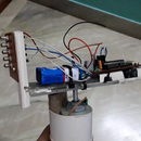
Step 5: FINAL SETUP

The set-up is ready now.
Step 6: ARDUINO CODE
You must have Arduino IDE installed in your laptop/PC.
You can download this code or you can get the code as I have described above. If you download this code then you have to put your authorization token (sent to your email while creating the project in your BLYNK App) in the code, I have left that part empty.


![Tim's Mechanical Spider Leg [LU9685-20CU]](https://content.instructables.com/FFB/5R4I/LVKZ6G6R/FFB5R4ILVKZ6G6R.png?auto=webp&crop=1.2%3A1&frame=1&width=306)


