

Introduction: House Alarm Internet Dialer for Aritech With Arduino


A very common Home and business Alarm used in many Europe countries are the Aritech series of alarm panels.
These were installed up to the early 2000 in their hundreds of thousands and many still exist in houses today - they are usually re-badged by the installers but they all have an easily recognizable keypad.
They are a fine system with many features - but, as they were developed before broadband, they lack the ability to connect to the Internet.
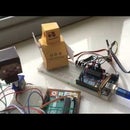
The image on this page is an animated image of the final system - it may not animate on mobile devices. Here is link to the animation
This project is about reverse engineering the alarm panel to add this missing functionality.
It will add the following:
- Ability to contact the panel and set/unset/view logs using any browser from anywhere eg. A Mobile Phone
- Have the Alarm system email you if the Alarm has gone off
- Allow you to enter engineering menus and configure the alarm panel remotely.
- Support CD34, CD62, CD72, CD91 and CS350 which are all the major models of this series.
Total cost of all parts will be much less than $20
Notes:
All photos and screenshots are original by myself (as per Instructables guidelines) - the code and circuit design were created by myself.
Step 1: The Plan


The plan was to get the Arduino to Emulate a Keypad.
The Aritech panel would think it was a standard keypad - but it would in fact be talking to an Arduino - this Arduino has no keypad or display - it instead has a webserver with which you can connect to over the internet.
The server delivers a website which uses websockets as the communication transport to give a very responsive emulated keyboard in html. Several key presses are buffered to give a response that rivals the original keypad.
The Arduino is installed at any point on the Aritech Bus - I placed mine inside the Alarm Panel cabinet - but you could attach to the Keypad end if your Ethernet connection is closer.
It is also possible to use an Ethernet to Wifi adapter if the Alarm Panel is a distance from any Ethernet connection - a wired Ethernet cable though, is much more preferable though for reliability.
Step 2: The Parts


The required parts list is:
- Arduino Uno R3 (amazon link £6)
- ie. a standard arduino - clones can be bought from $5 upwards - Arduino Ethernet shield (amazon link £7)
- Another standard Arduino part - Amazon sell them for aprox $10 upwards - DC-DC power supply (link or link) about $4
Used to convert the Panels 12Volts to a stable 5Volts
The following are optional depending on which circuit you build
- Two Transistors BC109 (or any similar general purpose NPN transistors such as 2N2222 or 2N2369)
- Resistors as specified in the schematic
- Diode
Any Diode (eg. IN4002 ) - Mini breadboard
You will also need the Engineer (Admin) Password for your Aritech Alarm.
If you don't have the password one option to consider would be to default the panel to factory settings and reconfigure it.
Powering the Arduino
The DC-DC power supply is the most critical component to get correct - don't be tempted to use cheap car 12V to 5V usb Adapters - the voltage of the cheaper adapters I tested contain a ripple voltage that can cause the Arduino to crash randomly.
I don't recommend using the Arduinos built in 9V socket when using the Ethernet adapter or using the Alarm Panels 5V power supply to power the Arduino - things will get hot! The DC-DC adapter specified above is very efficient and provides a very stable 5V without heating up - I apply this 5V to the 5V pin of the Arduino.
If you decide to power from a mains powered usb adapter (eg. phone adapter) and not the module above - you will need make sure this adapters output GND is connected to any of the Alarm Panels ground; as everything needs to share the same GND.
Breadboard Choice
I used a small mini-breadboard to prototype the system.
If you make it neat the breadboard is good enough to use as a solution - but after you are sure everything is working you may like to make up a soldered version using, for example, the small prototype shield shown in the last photo.
Step 3: The Build (breadboard Version)


Here are the two options to choose from.
1) Direct to panel.
This is the easiest method. Its very efficient and reliable. The only downsides are - it requires soldering 2 wires to the Aritech main board and some may not like soldering direct to the panel. Also, the two wires from the Arduino to the panel for this option should be fairly short (about 30 cm max is about right) so the Arduino will need be in or near the Alarm cabinet. This option is detailed on the next (optional) step.
-or-
2) Custom Arduino to Aritech Circuit
This involves creating a custom interface board to make the Arduinos outputs capable of connecting to the Aritechs 12v keypad bus. The circuitry is designed especially so that it will not interfere with any other keypads on the bus. It requires 2 transistors and a few supporting components. The wires can be as long as you like.
The circuit shown above is the interface required for the Arduino to connect to the 4 wire bus.
A photo is shown of the breadboard (second photo) for an idea on how to connect up - This breadboard was used for development- please refer to the schematic (first photo) when building up your circuit board or breadboard.
The Aritech panel uses a four wire keypad bus - you can connect to any point on this bus - eg. at either the Keypad end or the Alarm Panel end.
The third photo is added just for interest and shows a circuit simulator I used when designing the circuit. The goal was to keep the parts count to a minimum; where possible the same part types and values and to make sure currents were kept low so no unnecessary heat is produced.
Ask questions if stuck and I can try help - I've tested this on the several panels I own here (I've been picking them up in boot sales when I see them) - As always with these projects I cannot be not responsible for any damage.
Step 4: The Alternative Hardware Version (easy One Diode Version)


This is an alternative to connecting to the 4 wire keypad bus. You can wire the project directly into the Aritech motherboard.
This requires having to solder two wires to the Aritech panel - but the advantage that the whole circuit now becomes just the One Diode - no transistors, resistors or breadboard necessary!
Images above show the connection points for attaching the wires.
With this method you need solder two wires to the largest chip (named 78C17) on the panel and connect them to the Arduino Pins 0 and 1 - the Pin 1 connection to the alarm panel must have a diode with the striped end(cathode) of the diode going to the Arduino - the non striped to the alarm chip.
The Pin connection depends on the alarm model - refer to the images above for the connection.
If you find it tricky to solder to the Pins (they are a little tight) solder the back of the panel or you can look along the track route to find an easier spot to solder. Shown in the third image of this step is the connection points I used for a CD72/CD62. Secure the wires using tape, hot glue or if you look carefully at my board you can see I soldered a small loop of wire to hold my cable secure.
You still need to power the Arduino using the DC-DC converter module mentioned already (set to 5v).
The Aritech Chip is 5V - same as the Arduino - so they are perfectly compatible.
Some later panels (eg. some CS350) use a surface mounted chip (the chip is very small and square). For these, the previous circuit may be best - but if you wish to try you may find it possible to solder to another place along the track leading from the microchip. If you look up the pinout of the PD78C17GF chip in its datasheet - the pin names to connect to are are "PC0/TXD" and "PC1/RXD".
Some "solder braid" may be useful to have on hand to clean up soldering mistakes if you are not used to soldering and apply too much solder.
Of course make sure everything is powered off while soldering it - for your safety as well as your alarms'.
Step 5: The Software

The code is quite complex - it was a major effort, and many tricks needed to be employed to squeeze all this code (keypad emulator, HTML webserver, HTML pages, Email client, Websocket Webserver, DES encryption and Base64 libraries) all into the tiny Arduino 32K flash and ram space.
All the code is hosted here:
https://github.com/OzmoOzmo/CastleAritechArduinoRK...
I will update the project code every while - so be sure to Fork the project so you get notifications when there is an update.
Just download all the files (important: use the download zip button rather than one file at a time).
To compile:
Place them in the same folder - and open the .ino file in Arduino IDE.
There is a config file in the project config.h - this is where you set your IP address, your email address and other options. It is well commented with all the options to choose from.
Compile and Upload to to Arduino. You will need disconnect the Arduino completely from the Alarm panel to program it- as anything connected to the Arduino RX & TX (pin 0 &1) can block the usb programming progress.
Also its best not to have the 5V power supply connected to the Arduino And the USB connected to a PC at the same time as both will be trying to power the Arduino.
Developers
Customising the software
I've found a Leonardo or Mega to be good for debugging as you get two serial ports - one for connecting to the alarm panel and one for sending debug messages back to the PC. But for normal operation - these or an UNO are perfect.
An oscilloscope & digital signal analyser were great tools to decoding the protocols used - I may document more on how I reverse engineered the protocol if anyone wishes.
Step 6: Connection and Final Notes

Installing
To install this project - you need to tell the Aritech Alarm panel there is a new keypad on the bus - Enter Engineering mode and select the option from the menus to "Install RKP" (Install Remote KeyPad).
If you have wired everything up ok you should see a new keypad being registered. The display will show a K for each keypad the Alarm sees (eg. KK*** for two keypads). Accept and exit Engineering menu.
Each physical keypad is assigned an ID (0,1,2 etc) - the code has this project set to be the Second keypad in the system - if you already have two keypads in your installation, you can change the Arduinos' place in the config file to be third or fourth.
To uninstall at any time is easy- just enter Engineering menu, remove the Arduino and run the "Install RKP" procedure again.
Handy Tip: If the Alarm Panel sees a keypad not responding it will sound the alarm - so if you you want to remove the Arduino at any stage, to work on it etc. - please enter the Engineer menus while you do so - the Alarm will Not sound when you are in Engineering Menu - your neighbours will appreciate this tip also.
To Connect to panel. Browse to the IP address: Check the config for the address setting - in this version of the software I've defaulted it to "http://192.168.1.205:8383".
It works with most modern browsers and mobile phones.
External Access:
You can make this accessible from outside the home by port forwarding on your home router and optionally using one of the free Dynamic DNS services. Just consider increasing the security below.
Network Security:
Especially if you are opening up access externally to the house- consider these tips to increase the difficulty of anyone guessing your password.
Make sure the User and Engineer(Admin)Password on the Aritech Alarm Panel are not the default passwords.
At a minimum you should enable "Code Tamper" on the alarm panel that will lock you out for a minute after 10 or so bad guesses to prevent brute force guessing of the password.
Consider having an Alarm Panel password 6 digits long (default is 4 digits long)
You could also change the Port to some random number (default is 8383).
Future Work
I also obtained a "HKC Secure Watch" Security Alarm Panel - and I have ported this project to it. I also have a more generic version with limited functionality that should work on other brands of alarms. You can find these projects on my list of Instructables.
Let me know how you get on with it :)

Participated in the
Arduino All The Things! Contest

Participated in the
Full Spectrum Laser Contest 2016

![Tim's Mechanical Spider Leg [LU9685-20CU]](https://content.instructables.com/FFB/5R4I/LVKZ6G6R/FFB5R4ILVKZ6G6R.png?auto=webp&crop=1.2%3A1&frame=1&width=306)


